VX Pro Series
Device Settings
Unico Config
1. Device Settings
1.1. Hardware Connection
This section details the physical connection process, including power, video inputs/outputs, and control interfaces.
Preparation
- Confirm all package contents, including the device, power cord, and video cables (e.g., HDMI, DP).
- Gather necessary tools, such as a screwdriver or network cable.
Connection Steps
- Power Connection: Connect the provided power cord to the device's power input and plug it into a power outlet.
- Video Input Connection:
- Connect the HDMI/DP/DVI output from your video source (e.g., a computer, media player) to the processor's input ports using the appropriate cables.
- ❗ Warning: Ensure the input signal resolution and refresh rate are within the device's supported range.
- Video Output Connection:
- Connect the processor's output ports (typically RJ45) to the cabinets.
- Control Connection:
- LAN cable connection (the most recommended): Use a network cable to connect the device's RJ45 control port to your computer's network port for software control.
- ❗ Warning: USB cable connection.
Interface Overview
Video inputs (VX400 Pro / VX600 Pro / VX1000 Pro share the same input configuration; VX2000 Pro differs):
| Connector | VX400/600/1000 Pro | VX2000 Pro | Max resolution |
|---|---|---|---|
| HDMI 2.0 | 1 (with LOOP) | 2 | 4096x2160@60Hz |
| HDMI 1.3 | 2 | 4 | 1920x1080@60Hz |
| DP 1.2 | — | 1 | 4096x2160@60Hz |
| 3G-SDI | 1 (with LOOP) | — | 1920x1080@60Hz |
| 12G-SDI | — | 1 (with LOOP) | 4096x2160@60Hz |
| Genlock | — | 1 (IN + LOOP) | — |
Video outputs:
| Connector | VX400 Pro | VX600 Pro | VX1000 Pro | VX2000 Pro |
|---|---|---|---|---|
| Gigabit Ethernet | 4 (2.6M px) | 6 (3.9M px) | 10 (6.5M px) | 20 (13M px) |
| 10G optical | 2 | 2 | 2 | 4 |
| Preview HDMI 1.3 | 1 | 1 | 1 | 1 |
| 3D connector | 1 | 1 | 1 | 1 |
Audio & control (all models): 1x 3.5mm audio input, 1x 3.5mm audio output, 2x Ethernet, 1x USB 2.0, 1x RS232; VX2000 Pro additionally provides a light sensor connector.
1.2. Device Communication Setting
The Unico software is installed on the control computer. The control computer can connect to the device in the following two ways:
- Via Ethernet cable: Connect the device and the control PC directly via Ethernet cable and set a static IP address for the device to let it and the control PC be on the same network segment.
- Via LAN: Connect the device and the control PC to the same LAN to ensure that both of them are on the same network segment.
The default IP of VX Pro is 192.168.0.10, so the control PC IP needs to be set as 192.168.0.xx like the following demonstration shown.
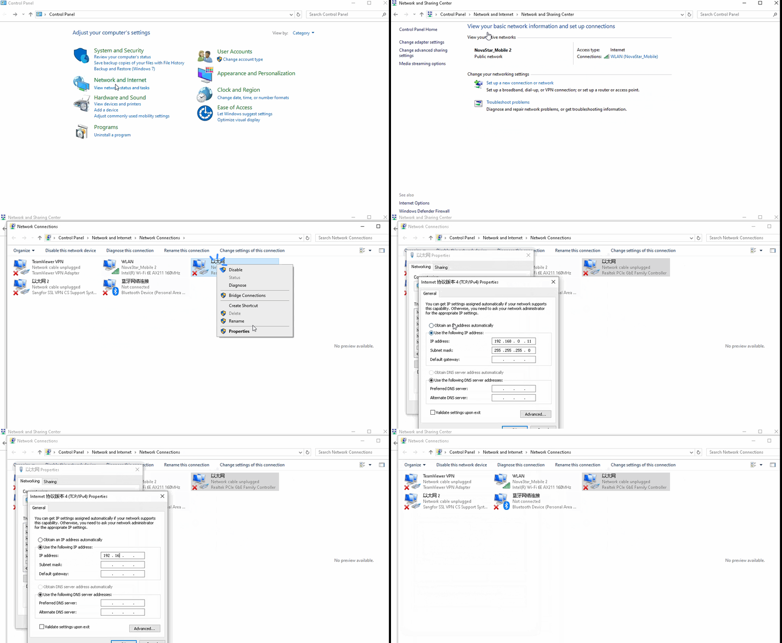
Device communication setting
2. Unico Config
2.1. VX Pro Upgrade
In the menu bar, navigate to Tools > Maintain. Select the Device tab and the target devices, and then do the following as required.
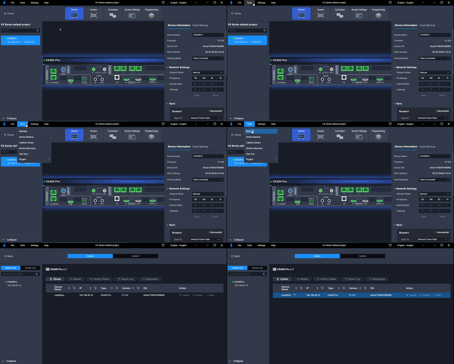
Tools > Maintain
Update
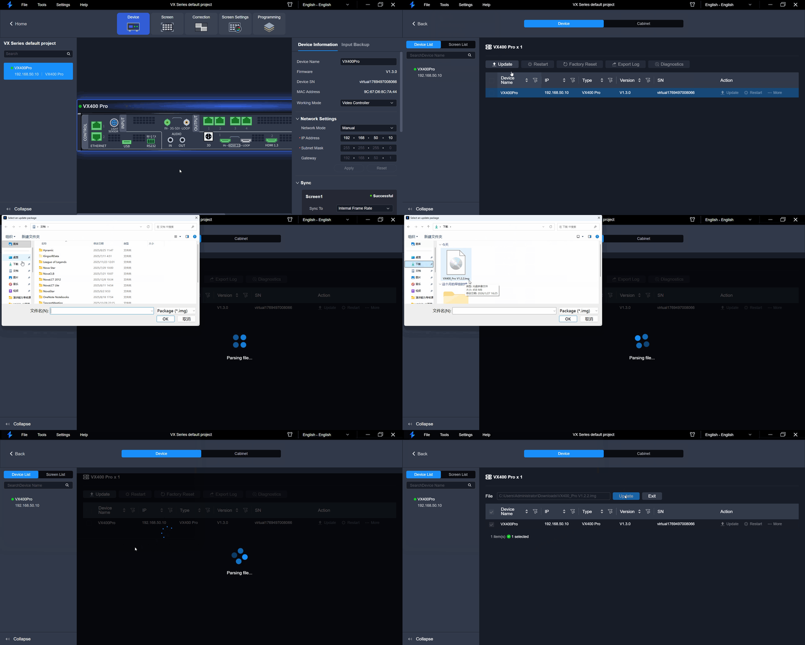
Update
⚠️ Note: During the update process, power-off and all operations are NOT allowed.
- Step 1: Click Update.
- Step 2: In the pop-up dialog box, select the update file (.img) and click OK.
- Step 3: Confirm the devices to be updated, and click the Update button.
- Step 4: In the pop-up dialog box, click Yes and wait until the update completes.
- Step 5: After the upgrade completes, click OK.
Restart
Click Restart. In the displayed dialog box, click Yes to restart the device.
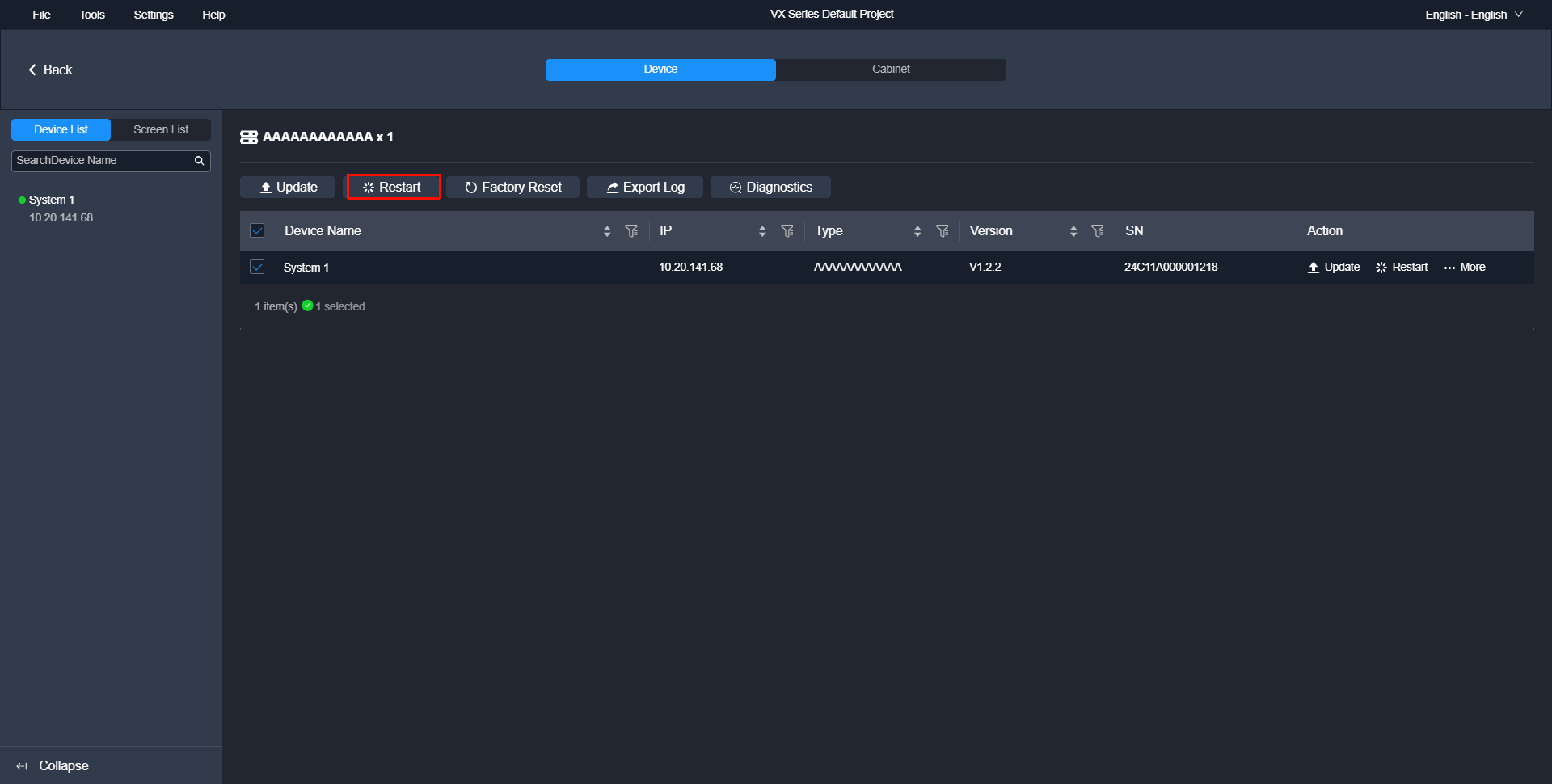
Restart
2.2. Device Management
Enter Device Configuration Page (VX400Pro as an example)
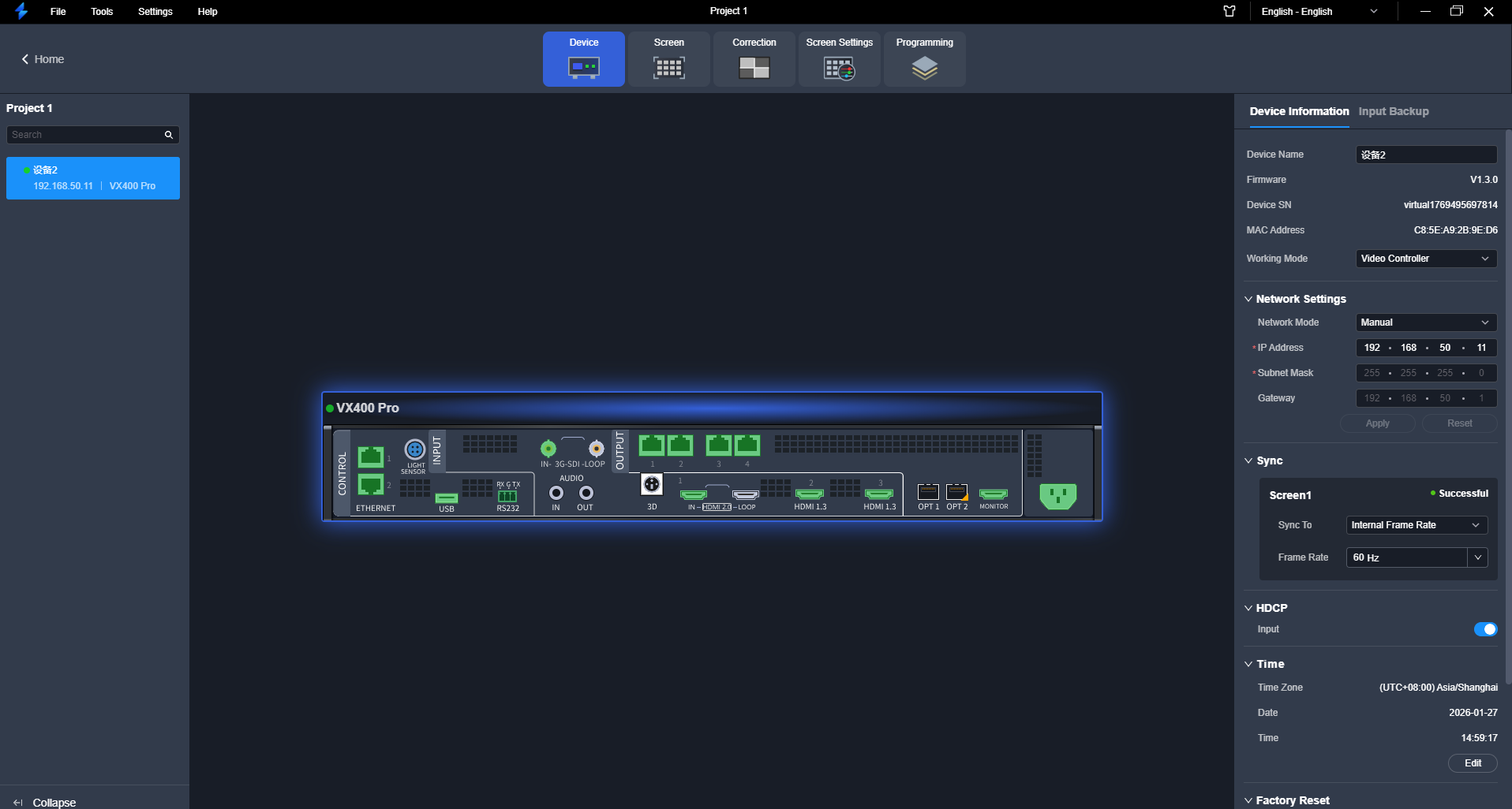
Device configuration page
Double click the image of the device front panel or click Enter on the right to enter the device configuration page.
Configure Device Properties
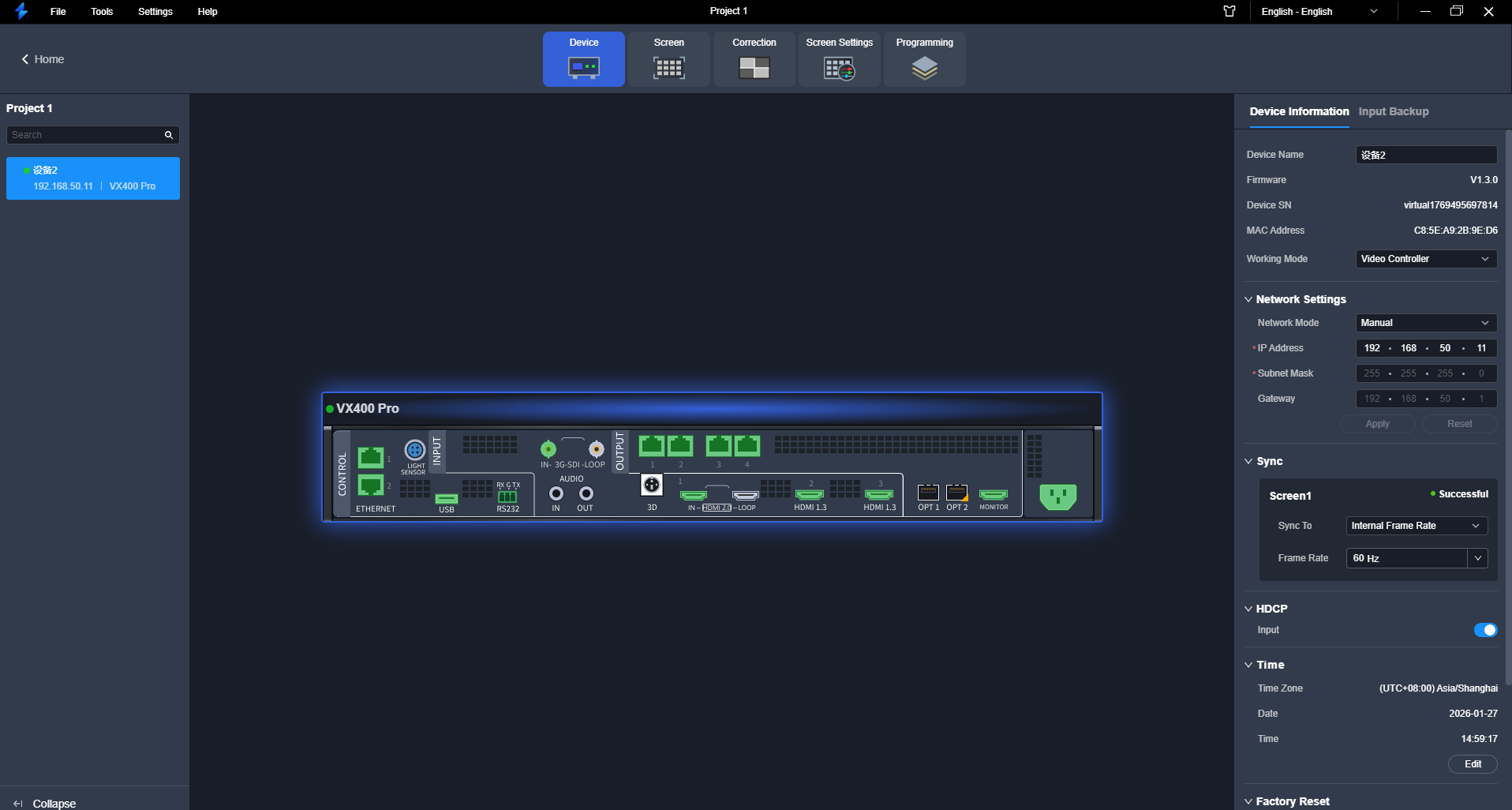
Device properties
Select the device on the left side of the device configuration interface and then configure the device-related properties on the right pane. On the left side, users can have the following operations:
- Rename device
- Configure IP address
- Configure Sync source: Select a sync signal to synchronize all the cascaded device units or synchronize the primary and backup devices to display the output images of all the units in sync.
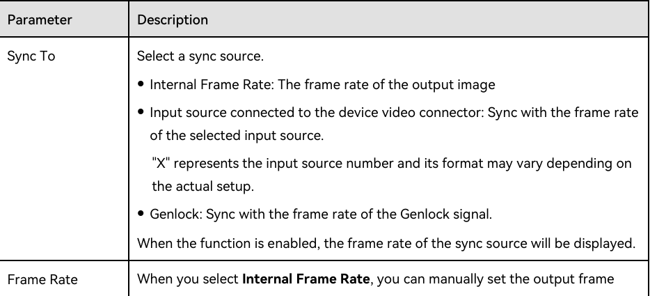
Sync source

Sync source configuration
- Configure HDCP: High-bandwidth Digital Content Protection (HDCP) is a form of digital copy protection to prevent copying of digital audio and video content as it travels across connections. When the accessed input source is an HDCP-encrypted one, you need to turn on this function to enable the device to transmit and process the source.
- Date and Time: Configure the time zone, date and time of the device. Click Edit and the parameters become editable. Set the time zone, date and time respectively, and then click Apply.
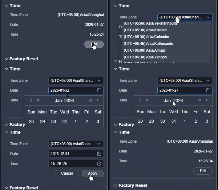
Date and Time
- Reset to Factory Settings: Reset the device data and settings to factory default values.
- Please do this with great caution.
- The reset action does not affect the device firmware version.
- Power-off is not allowed during the reset process.
- The device will restart automatically after the reset is completed.
- Standby Mode: Enabling standby mode can effectively reduce energy consumption caused by screen heat generation. Once the standby mode is enabled, the output image will go black and the output volume will be adjusted to 0. The device LCD screen will also be locked, while other parameters remain unchanged.
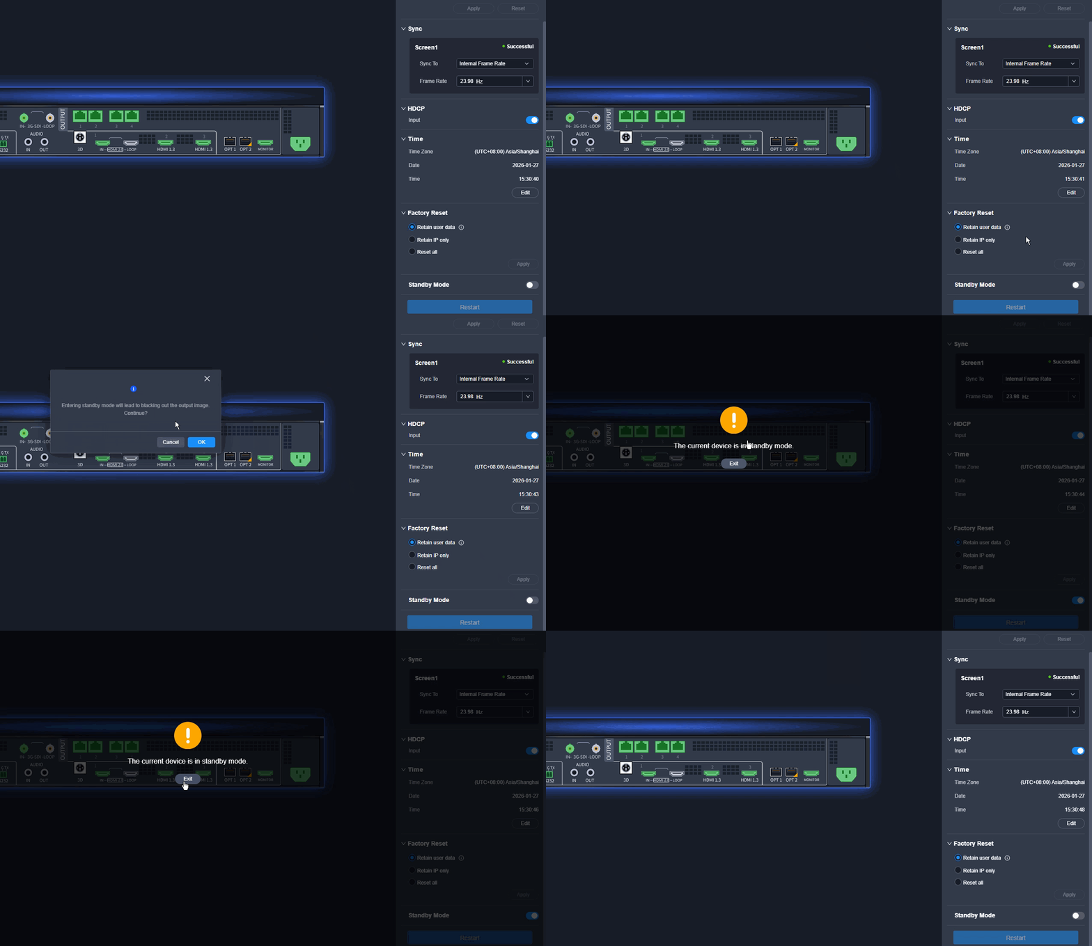
Standby Mode
- Restart Device: Click Restart, and then click Yes in the displayed dialog box.
Configure Input Properties
Click the target input connector on the graphical device rear panel and then set the input related properties in the property area on the right pane.
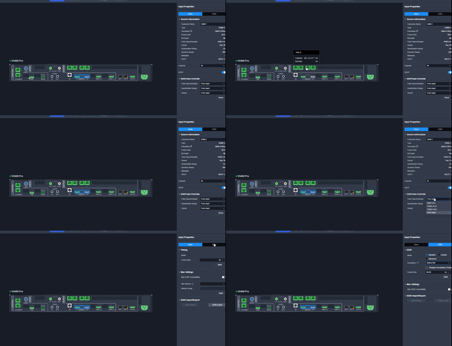
Input properties
(1) View Input Source Info
View the basic properties of the input connector and change the input connector name.
(2) View OPT Source Info
View the basic properties of the OPT source and change the OPT port name.
- The device working mode is set to Video Controller.
- OPT 1 and OPT 2 is connected to the OPT ports on the front-end video processor via optical fiber cables. Additionally, a fine signal is connected to the front-end device.
- Each OPT support the transmission of 1x DL or 2x SL sources.
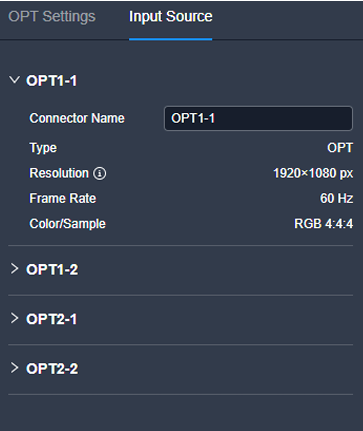
OPT source info
(3) Set Input Connector Capacity
Switch the input connector capacity as desired.
⚠️ Note: When a connector is configured for hot backup, you can no longer switch its capacity.
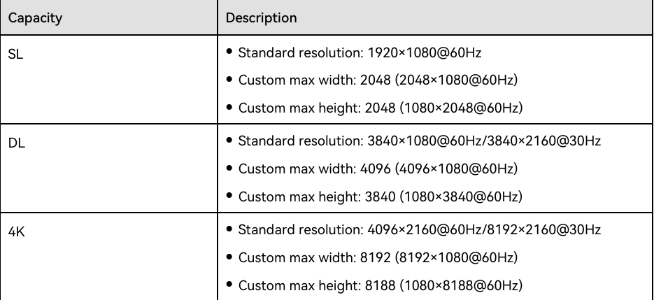
Input connector capacity
(4) Configure InfoFrame Override Parameters
Configure the InfoFrame override parameters of the input source, so that the device can use it when doing some calculations. This action does not change the parameter values that come with the input source.
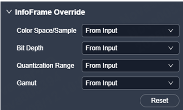
InfoFrame override
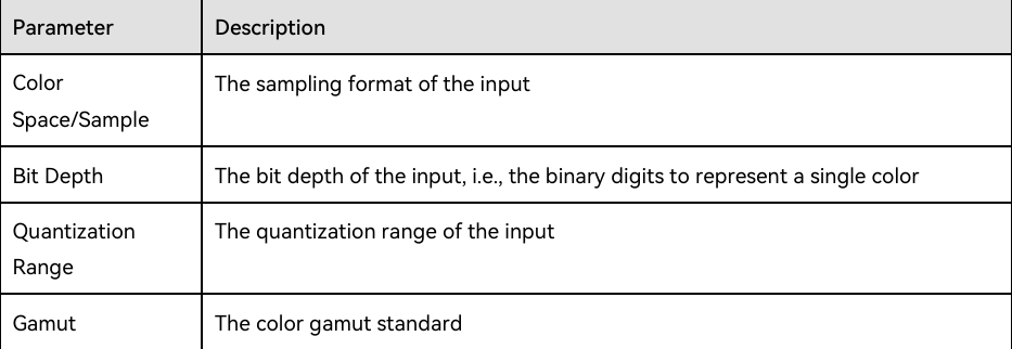
InfoFrame override parameters
(5) Set HDR
HDR is the abbreviation for High-Dynamic Range. HDR function can greatly enhance the display image quality, allowing for a more clear and vivid image when the device is used together with the specified receiving cards.
⚠️ Note: Only VX2000Pro can be applied.
Prerequisites
- Use the layer 1 source as an HDR source.
- An HDR source (HDR10/HLG standard) must be used to realize optimal HDR effect.
Notes
- An HDR source can be connected to the HDMI 2.0 or 12G-SDI connector only.
- The HDR and 3D functions cannot be used together.
- Using the HDR function paired with receiving cards of different models will reduce the device loading capacity by half or quarter because the HDR input source is 10-bit. Please work out a connection solution in advance.

HDR settings
After the HDR source parameters are successfully set, you need to adjust EOTF.
⚠️ Note: When you enable the HDR function, the receiving card supporting this function should be used together. For the specified receiving card model and related information, please refer to our official website (www.novastar.tech).
(6) Configure EDID
Configure the resolution and frame rate of the input. You can select the standard resolution provided by the device, customize a resolution, or set the advanced parameters.
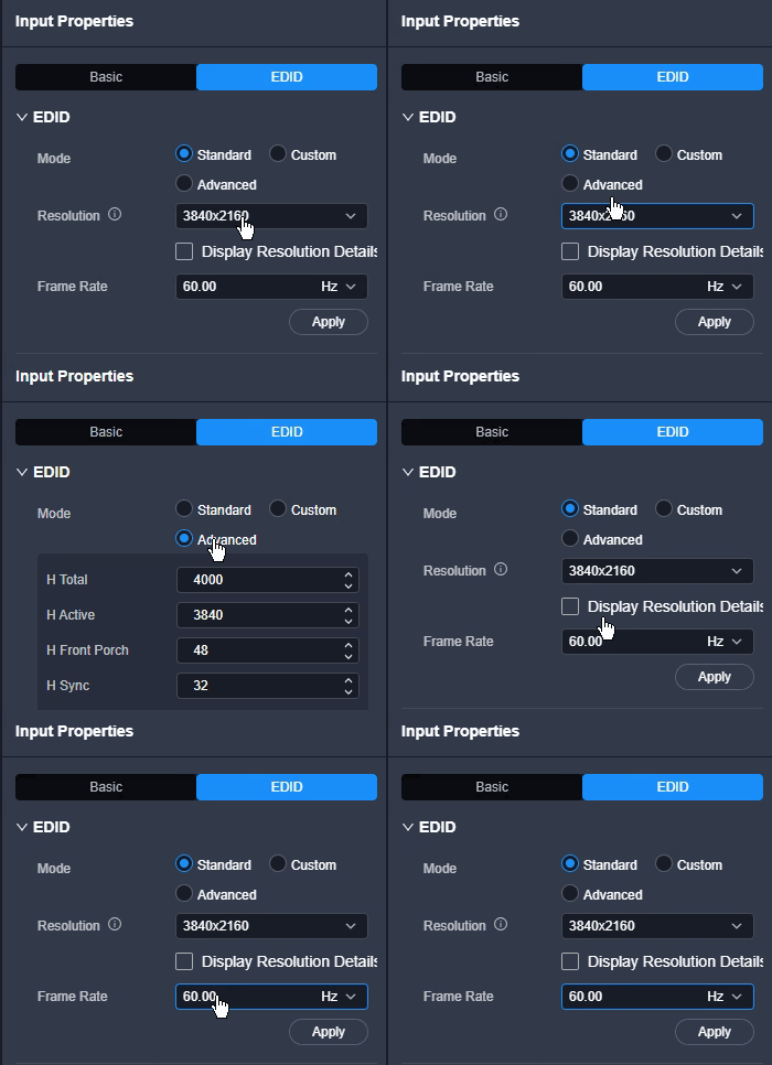
Configure EDID
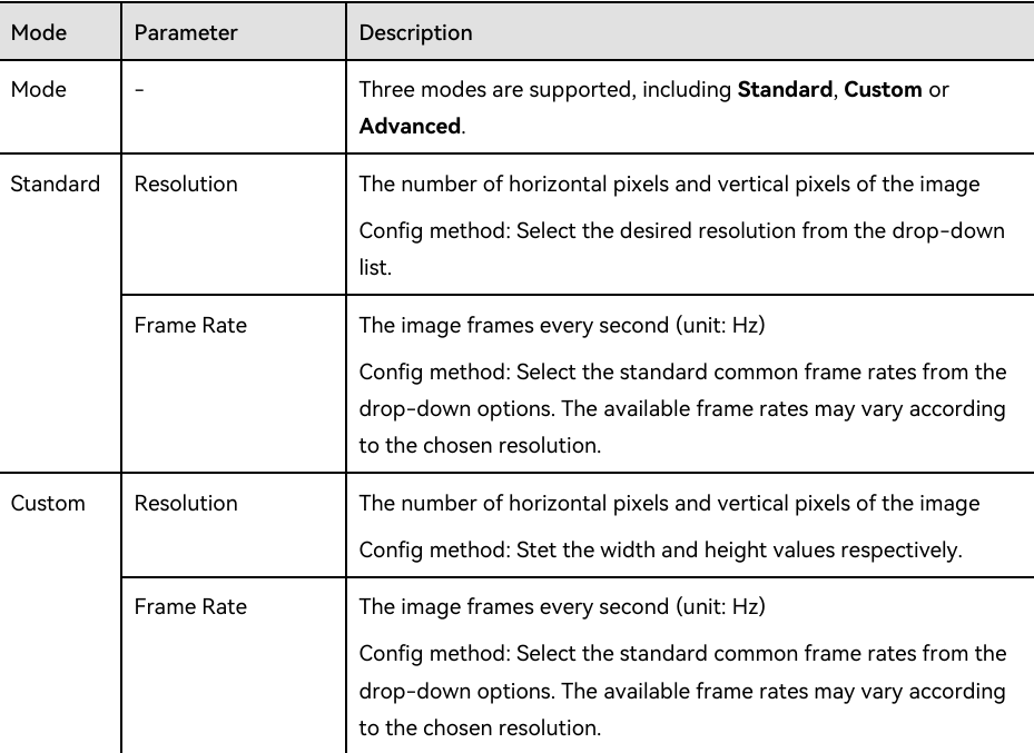
EDID settings
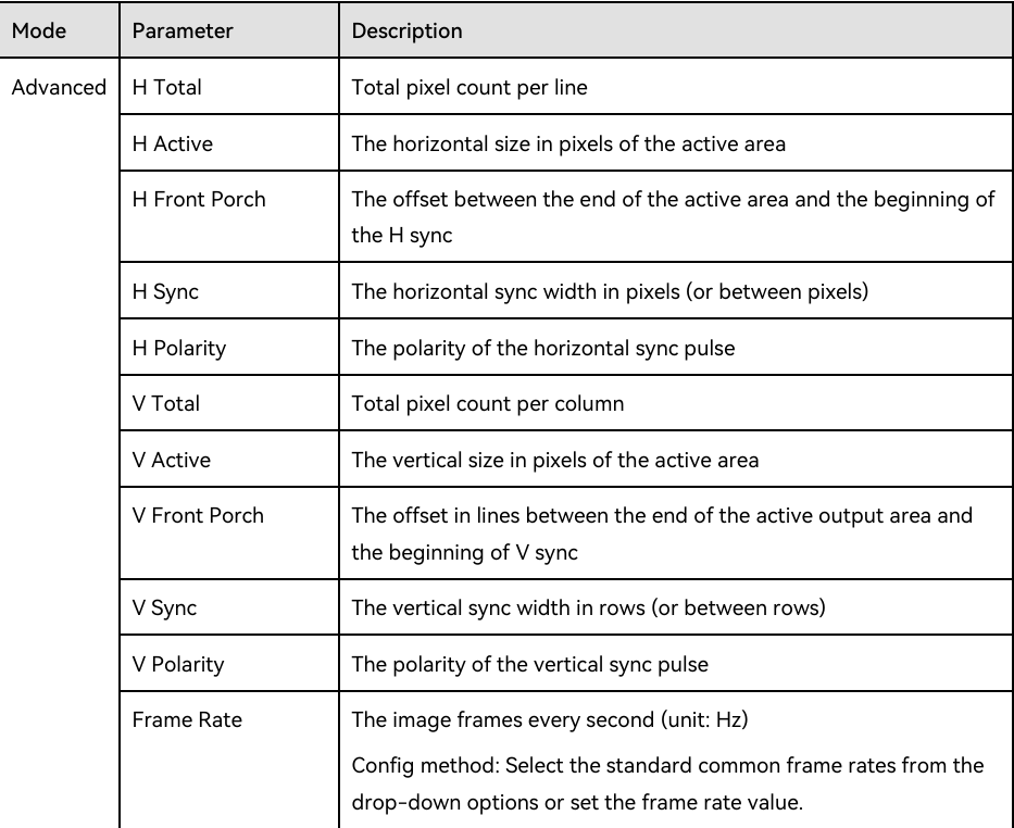
EDID advanced parameters
(7) Configure Compatibility with Mac
When the device is incompatible with the EDID of a Mac system, you may activate this feature to resolve the issue.
Configure Output Properties
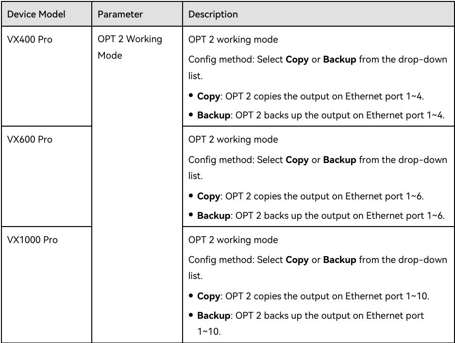
(1) Set OPT Ports: Set the OPT working mode and loop mode.
Prerequisites: The device working mode is set to Video Controller.
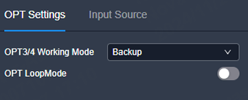
OPT working mode
OPT loop mode
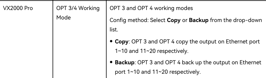
OPT ports
⚠️ Note:
- After the OPT working mode is set to Copy, the OPT ports on the graphical device panel will be highlighted.
- After the OPT working mode is set to Backup, the backup icons will be displayed at the bottom right corner of the OPT ports on the graphical device panel.
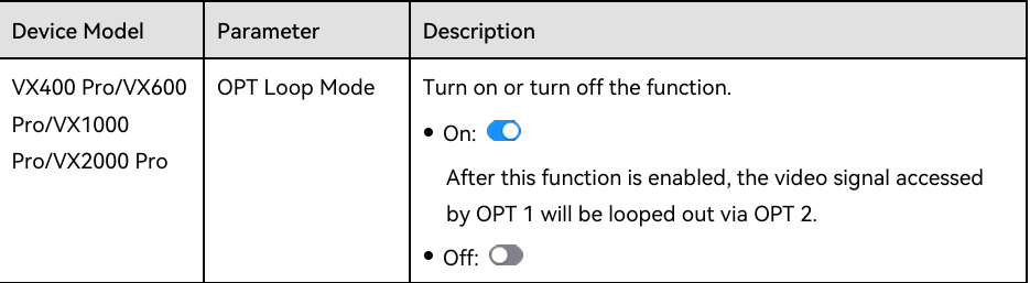
OPT backup icons
(2) Set Monitoring
Real-time display of the output image via the monitor connected is supported. You can monitor whether the output is normal and adjust the display ratio of the monitoring image on the monitor to avoid image distortion.
⚠️ Note:
- When you enable the loading capacity expansion of 2.6 million pixels, monitoring settings are not allowed.
- Only the VX2000 Pro supports the setting of the monitoring image definition.
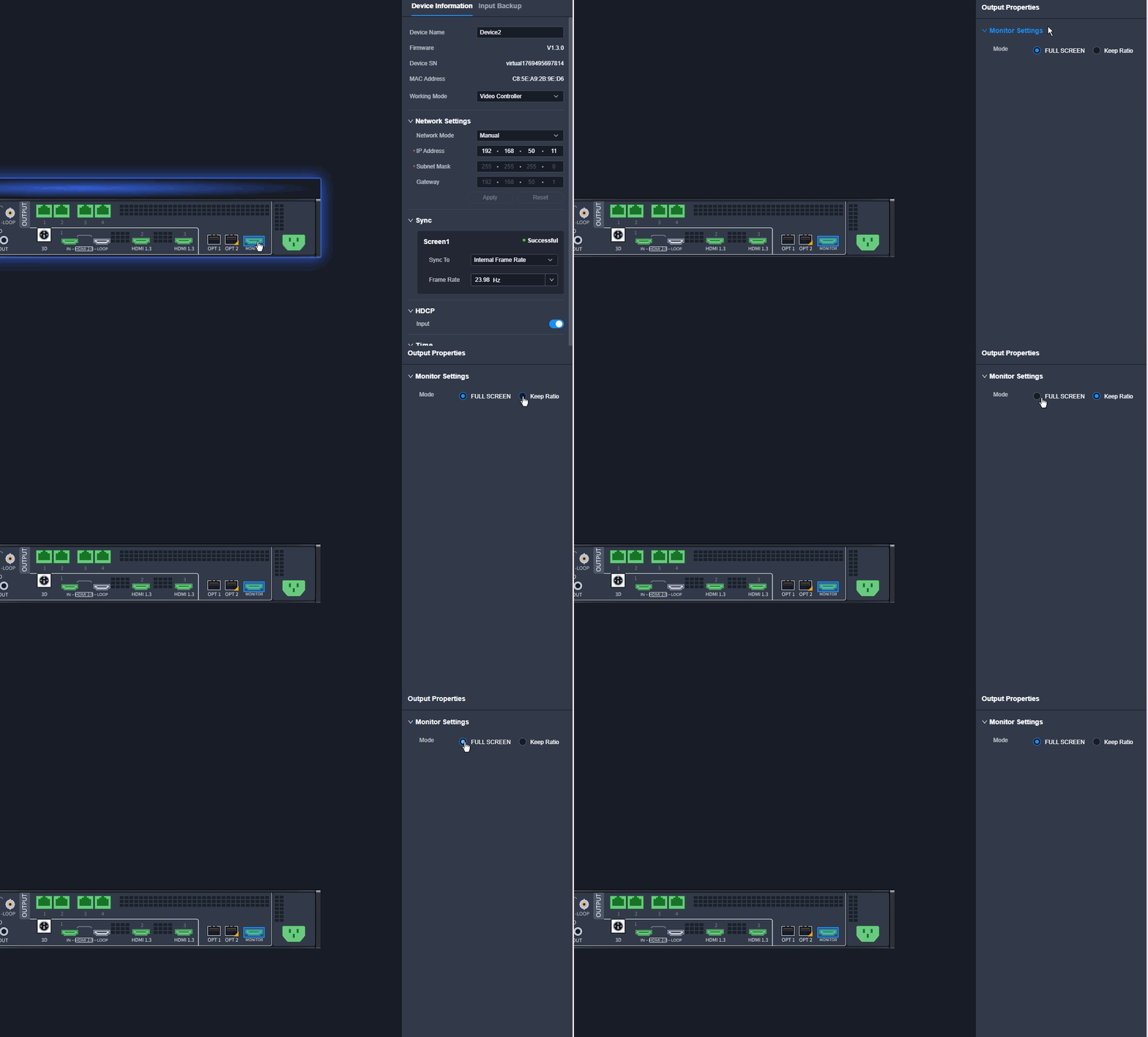
Monitoring
Click the Monitor connector on the device rear panel, and then set the following parameters.
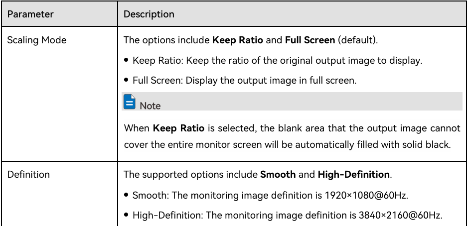
Monitoring parameters
2.3. Cabinet Configuration
2.3.1. Configure Cabinet Properties
View Cabinet Library
View the online cabinets or cabinet configuration files in the cabinet library. Click New to upload the cabinet file to the local pack or device pack, or add the virtual cabinet to the local pack. For detailed operations, please refer to Manage Cabinet Library.
2.3.2. Change Cabinet Resolutions and View Cabinet Info
2.3.3. Configure Empty Cabinets
Operation Procedure
- Step 1: Click Screen at the top of the page to enter the screen configuration page.
- Step 2: Select the desired screen from the screen list on the left.
- Step 3: In the function bar, click and then click Add Cabinet in the popup window.
- Step 4: Select the desired cabinet existing in the cabinet library from the drop-down list below Select Cabinet.
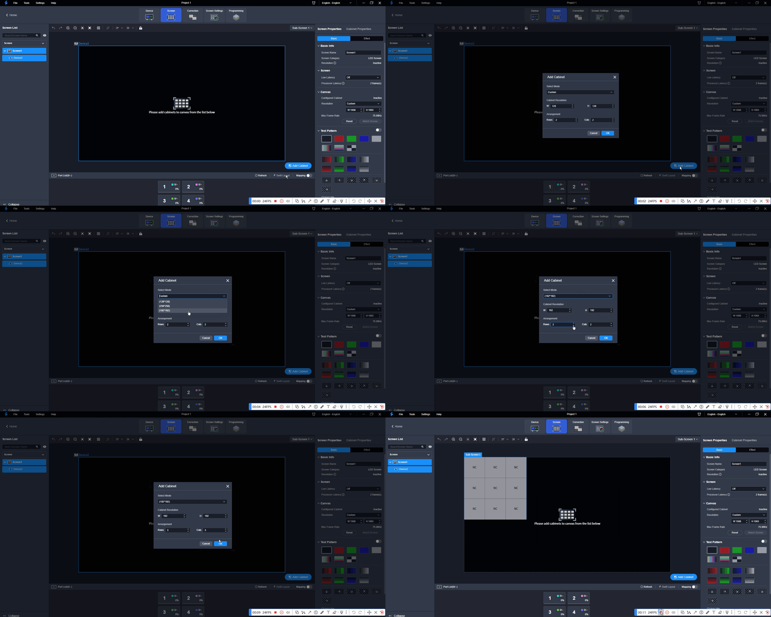
- Step 5: (Optional) If no cabinet configuration files (.rcfgx) are imported to the cabinet library, you can set the width and height for the empty cabinet.
- Step 6: Set the rows and columns of cabinets. After settings are done, click OK to confirm.
- Step 7: In the topology area, click the left mouse button to add cabinets with the set rows and columns.
- Step 8: Select the desired Ethernet port and drag or click the mouse in the empty cabinets to complete the wiring.
- Step 9: Select other Ethernet ports and continue wiring until all cabinets are connected.
- Step 10: Connect the on-site cabinets based on the configured topology.
⚠️ Note: When configuring the empty cabinet, you can leave the desired cabinet without wiring as shown below based on the on-site screen loading requirements.
2.3.4. Maintain Cabinets
In the menu bar, navigate to Tools > Maintain. Select the Cabinet tab and the target cabinets, and then do the following as required.
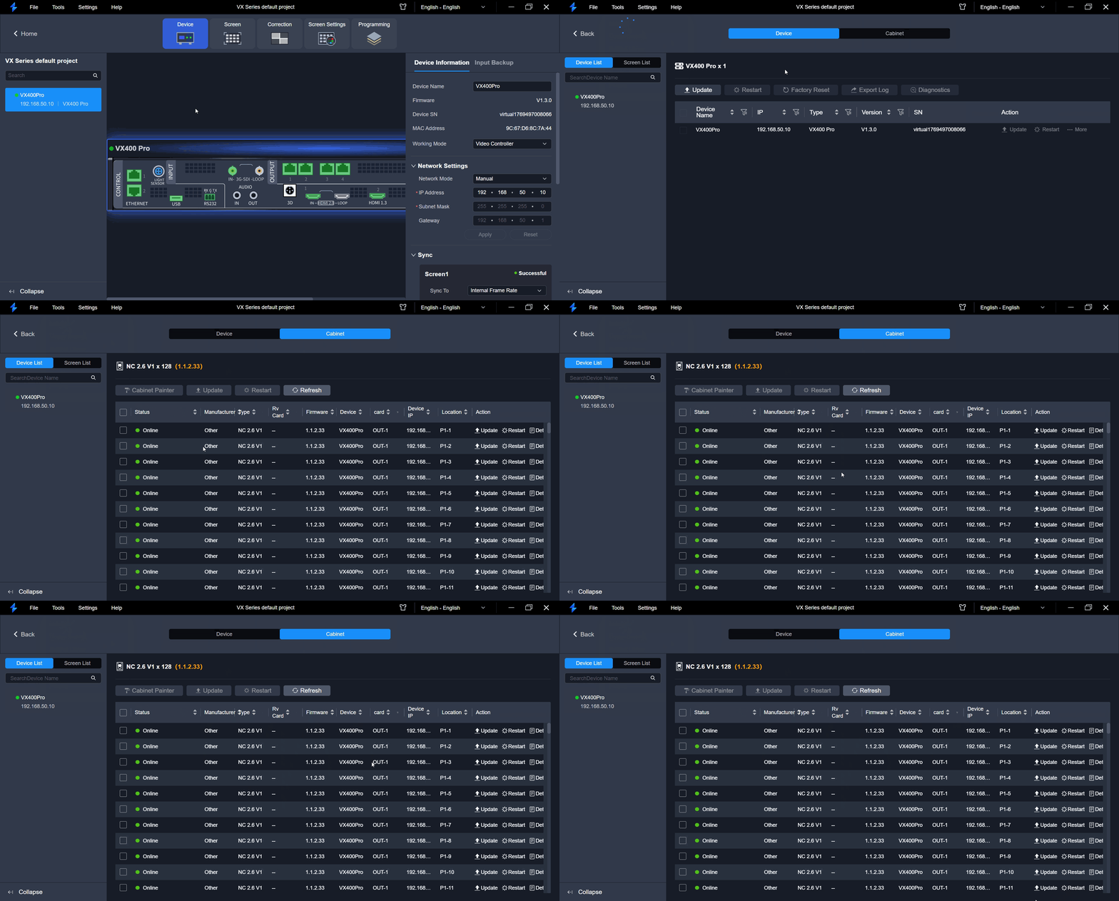
Maintain Cabinets
View the cabinet online status, cabinet manufacture, cabinet model, receiving card model, receiving card firmware, associated device, card (only applicable for card-based device), device IP and cabinet position.
View Receiving Card Firmware Information
- Click Details to view the FPGA and MCU versions of the receiving card.
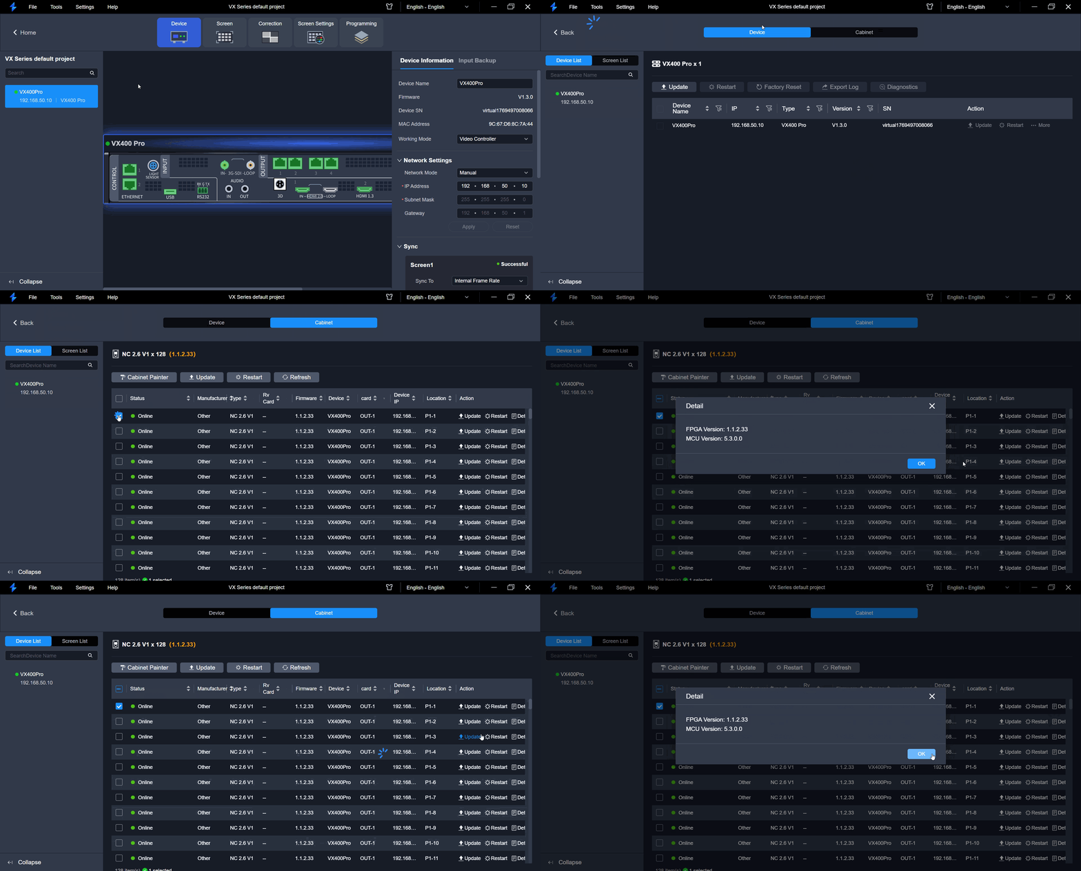
Receiving card firmware
Cabinet Painter
- Click Cabinet Painter and select one or more cabinets so that other cabinets can have the same firmware program and configuration file as the selected cabinet.
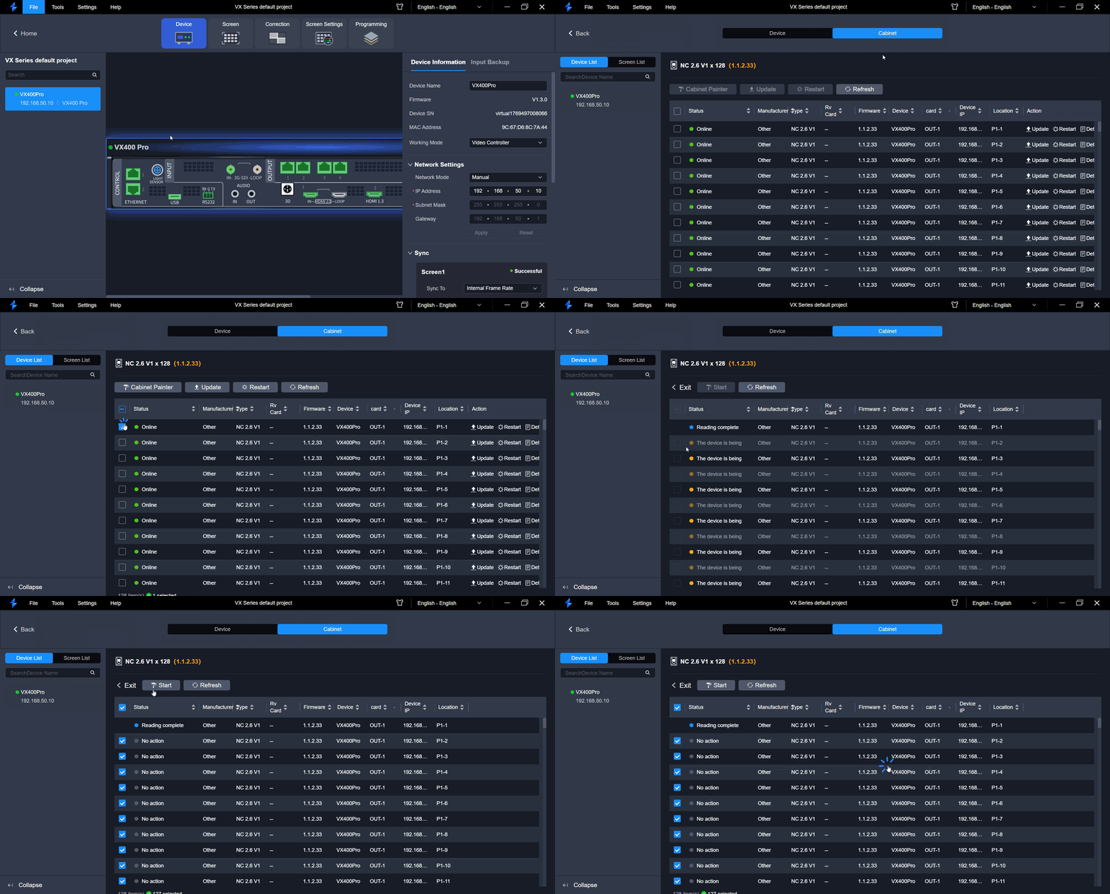
Cabinet Painter
Update Cabinet Configuration Files
- Select one or multiple cabinets, then click Update.
- Select the desired update method in the pop-up window:
- Cabinet Library: Click Import to upload a NCP / rcfgx file. You can select the import objects (multiple selections are possible) from local pack or Device pack. Then select the imported NCP / rcfgx file and click Update.
- Firmware Program: Update the firmware of receiving card in image format, and then click Update.
- Configuration File: Upload a NCP / rcfgx file, and then click Update.
- Image Quality File: Import an adjustment parameters of the image quality. Upload a file in vglcx format, and then click Update.
⚠️ Note: The supported cabinet update method depends on the receiving card model.
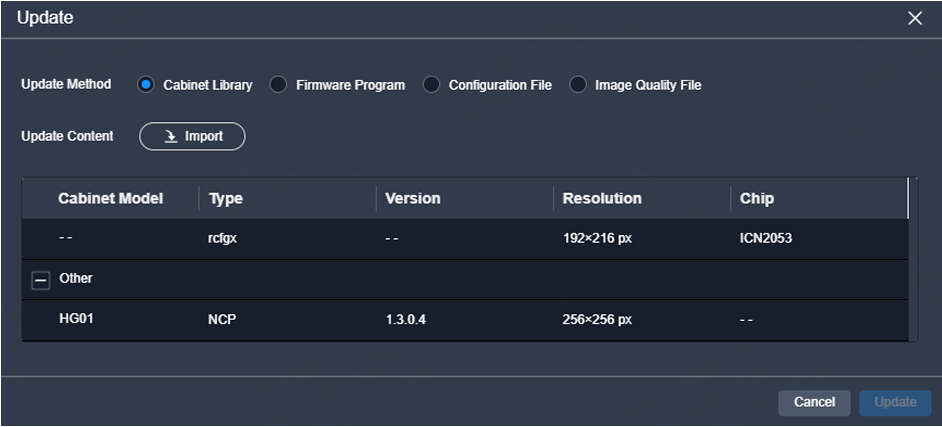
Update cabinet configuration
Refresh and Restart
- Restart Cabinet: Click Restart. In the pop-up dialog box, click OK to restart the cabinet.
- Refresh Cabinet Info: Click Refresh to refresh the cabinet information.
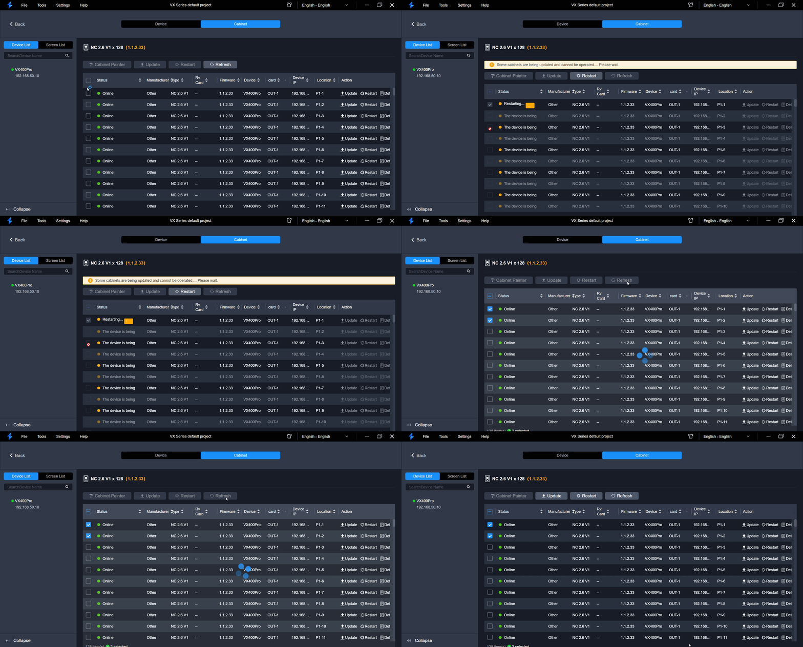
Refresh and Restart
2.4. Screen Connection
Configure Screen Topology
Configure the cabinet topology to complete the wiring connections of the physical or empty cabinets.
Operation Procedure
- Step 1: Click Screen at the top of the page to enter the screen configuration page.
- Step 2: Select the desired screen from the screen list on the left.
- Step 3: In the Ethernet Port List area, select an Ethernet port and then drag and click the mouse in the topology area to add cabinets.
- Step 4: Select other Ethernet ports and continue to add cabinets until all cabinets are connected.
- Step 5: For cabinets that have the same size and consecutive serial numbers, if you want to change the cabinet connection topology, select the cabinets and then select a quick topology under Quick topo in the properties area. For other cabinets, skip this step.
- Step 6: Do any of the following to arrange and align the cabinets and cabinet groups to let the cabinet positions meet the display requirements.
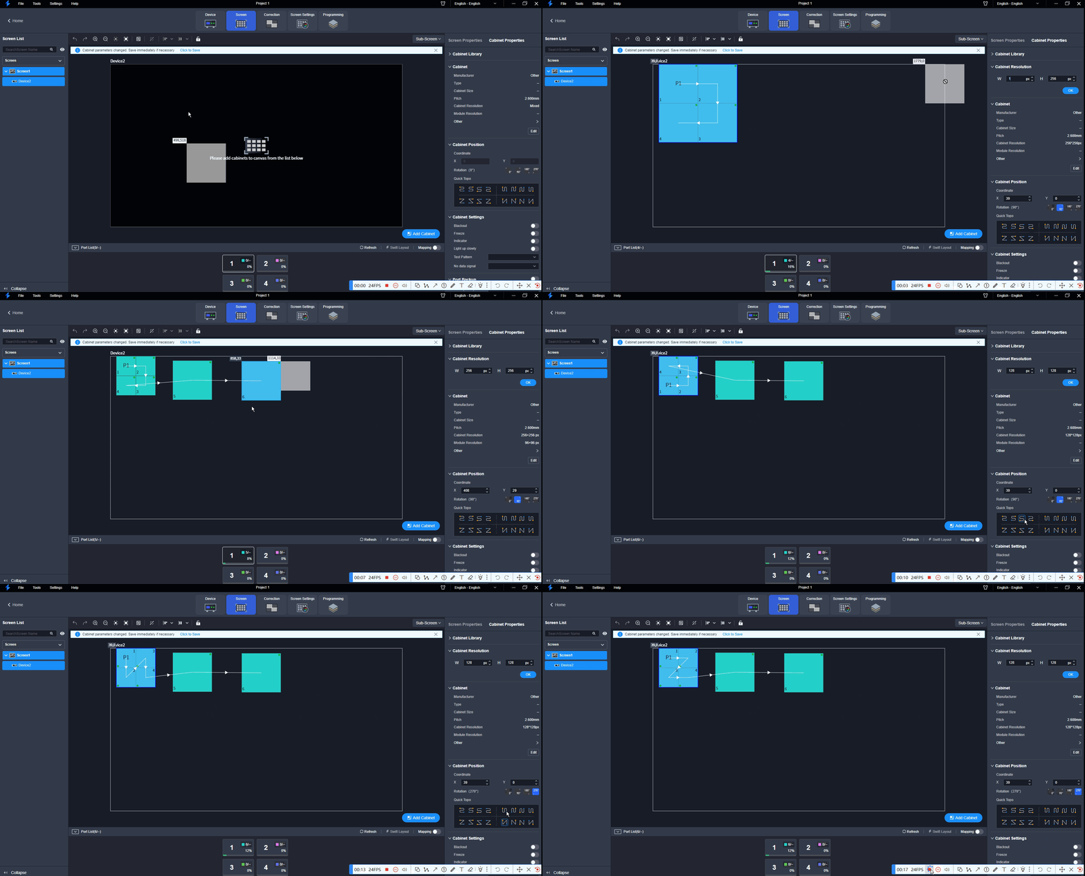
Screen topology
Cabinet alignment
2.5. Screen Settings
2.5.1. Configure Screen Properties
Set the screen-related properties in the property area on the right pane.
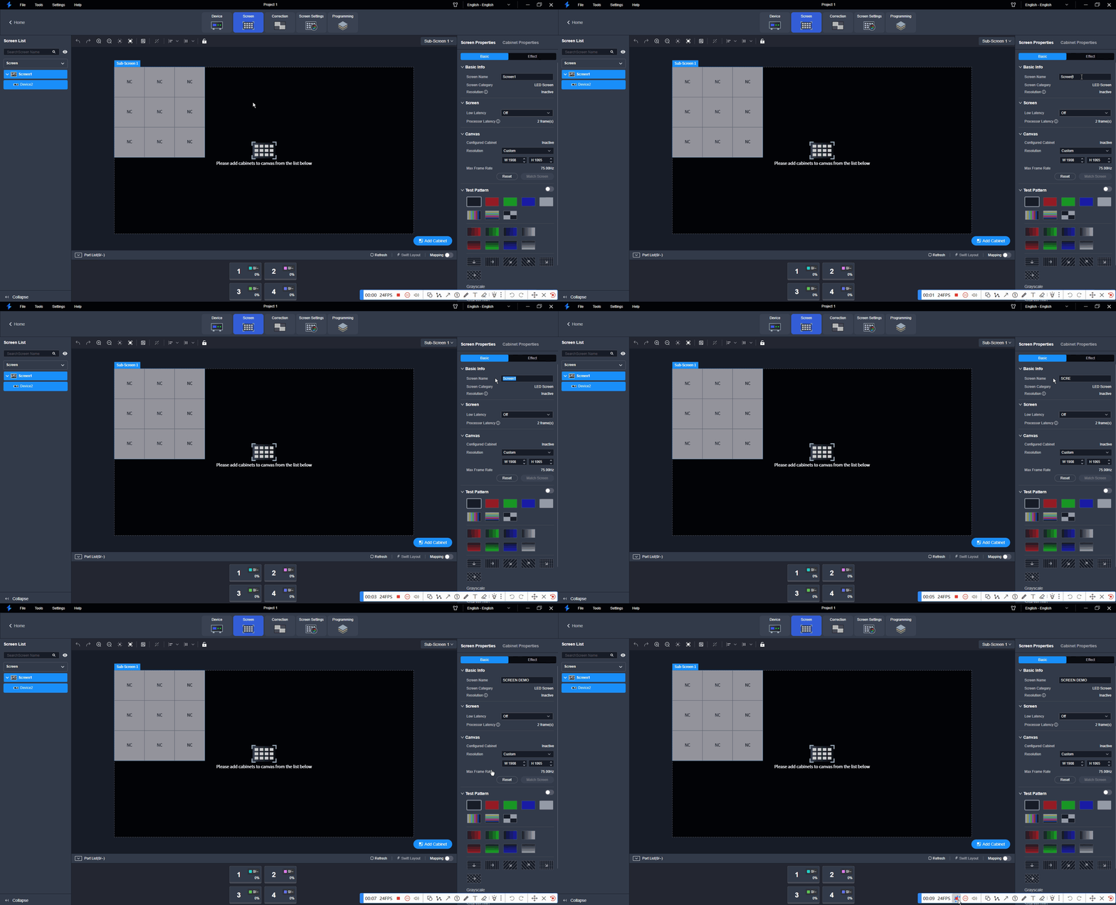
Screen properties
2.5.2. Configure Low Latency
When the input source travels from where it comes to the processing device, sending device and then the receiving card, latency exists inevitably. Turning on this function can effectively help to reduce the latency from the input to output.
⚠️ Note: All cabinets loaded by Ethernet ports must be aligned at the top of the circumscribed rectangle.
On the Basic tab interface, configure the following parameters.
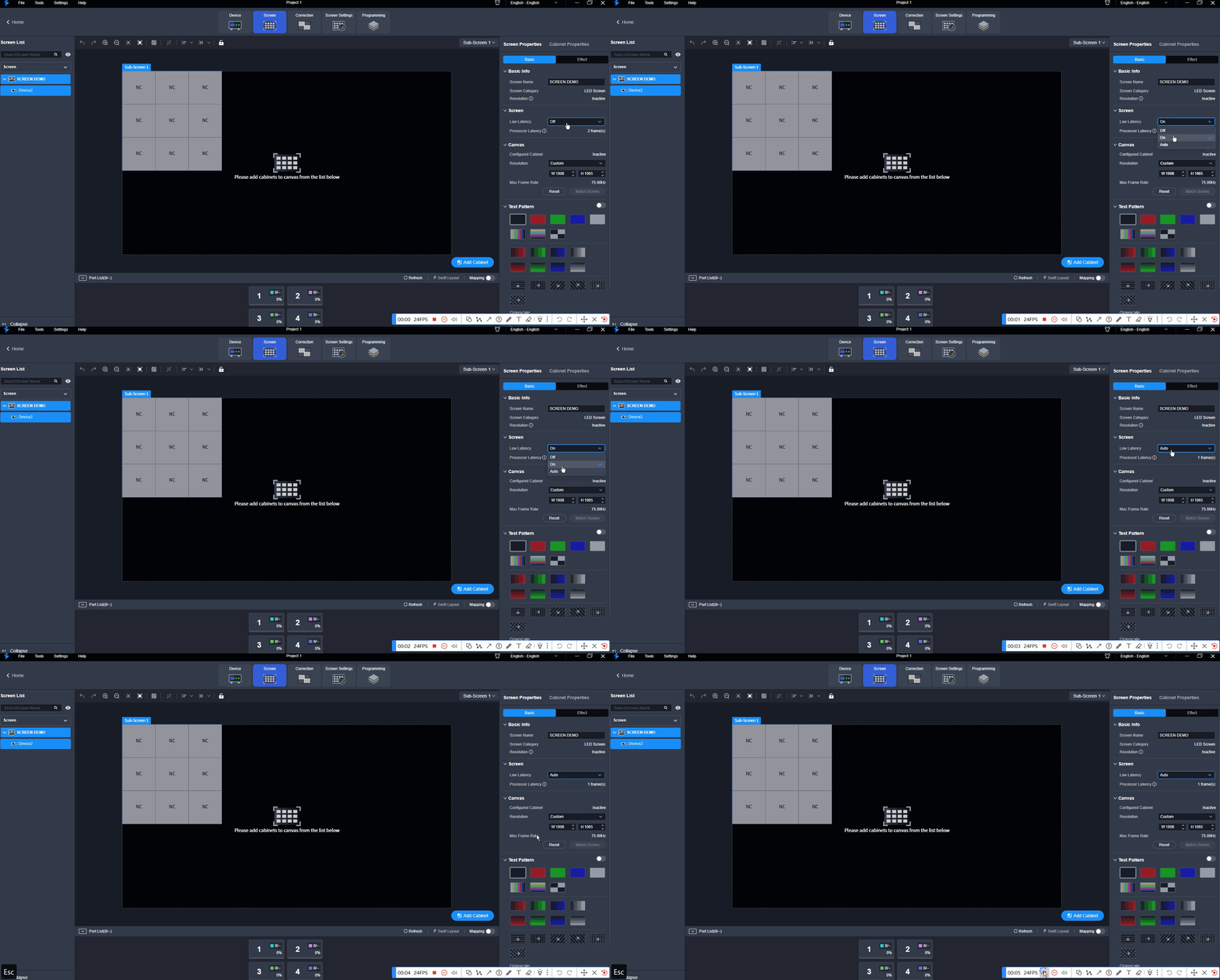
Low latency
2.5.3. Set Canvas Size
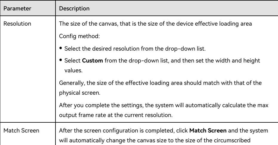
Canvas size
2.5.4. Configure Test Patterns
Test patterns are used to check the connection relation between the output connectors and the screen, and check whether the screen display is good.
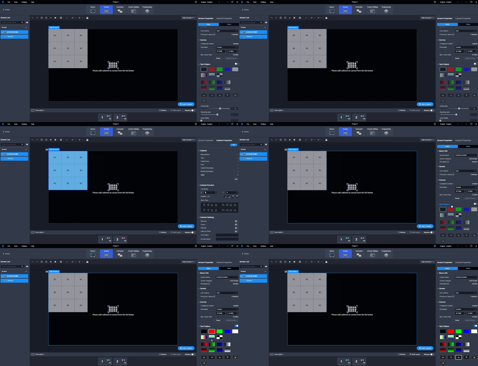
Test patterns
2.5.5. Configure Output Color
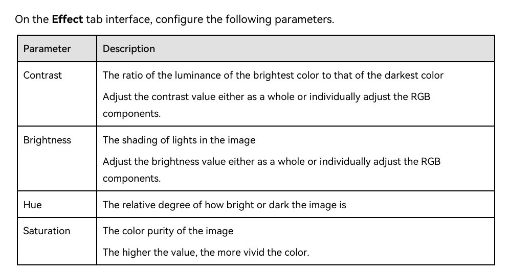
Output color
Adjust Image Quality
Adjust Brightness and Gamma
Adjust the Gamma value and brightness of the output to enhance the overall image quality of the LED screen.

Brightness and Gamma
Set LED Image Booster
Applicable Products: VX400 Pro, VX600 Pro, VX1000 Pro, VX2000 Pro

LED Image Booster
Adjust EOTF
Applicable Products: VX2000 Pro
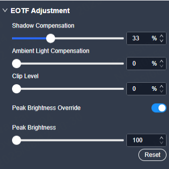
Adjust EOTF
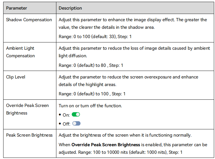
EOTF settings
Adjust Output
Set Output Bit Depth
Applicable Products: VX2000 Pro. When you use the HDR function, setting output bit depth to 10bit is required to achieve optimal display effect.

Output bit depth
Configure 3D
Prerequisites
- Video source format: Side-by-side, top-and-bottom or frame sequential.
- When paired with the EMT200 Pro, it is recommended to use a 3D source of 60Hz to enjoy an optimal experience.
Notes
- When the 3D function is enabled and the video source format is Side-by-Side or Top-and-Bottom, the device output capacity will be halved.
- When the 3D function is enabled and the video source format is Frame Sequential, you need to manually set the output frame rate which must be the same as the input frame rate.
- The 3D function and input cropping cannot be enabled at the same time.
- After enabling the 3D function on the Screen Settings page, 3D switches of all the layers will be toggled on. If you want to use a 2D layer, please toggle off the 3D switch of the desired layer in the property area of the Programming page.
- The 3D effect follows the layer. The output area where a 3D layer is located always displays the 3D effect.

3D settings
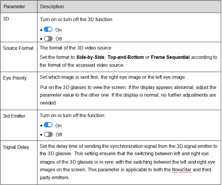
3D configuration
Check Load
Check the capacity usage of each Ethernet port of the device.
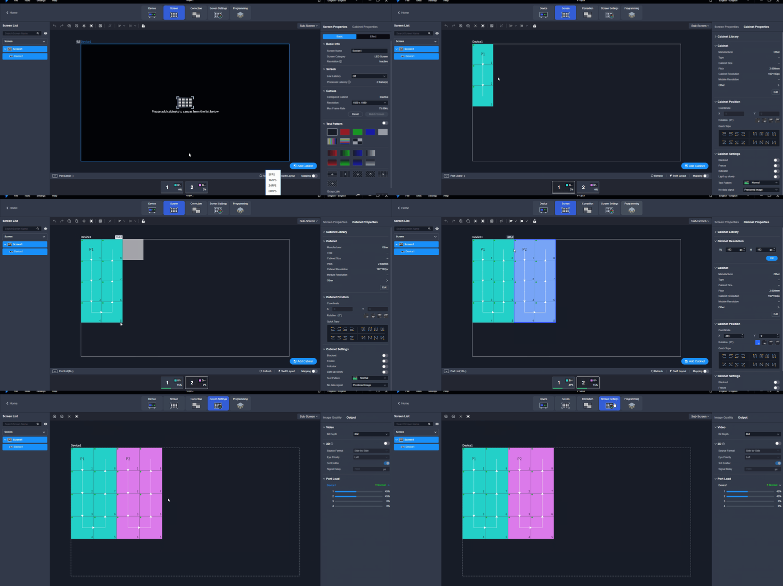
Check load
2.6. Programming
Add Layers
Make sure the device is in Video Controller mode before adding layers. The maximum number of layers that can be added depends on the connected device.
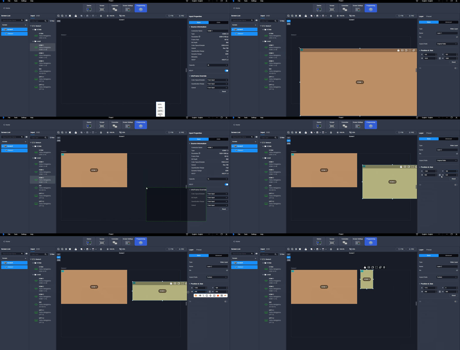
Add layers
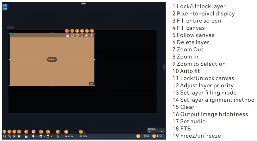
Layers
Configure Video Source Properties
Mosaic Source Settings
Both HDMI and OPT sources support mosaicing.
View Mosaic Source Info
Applicable Products: VX2000 Pro. Prerequisites: A mosaic source has been configured and its signal is fine.
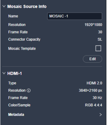
Mosaic source info
Configure Mosaic Sources
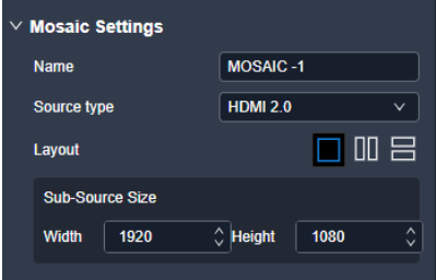
Configure mosaic sources
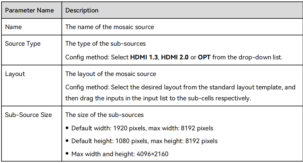
Mosaic source settings
Configure USB Source Properties
Select a USB source in the input list and configure relevant properties on the USB Playback Settings tab interface. The models of devices that support USB playback and the corresponding output resolutions for USB sources are listed below.
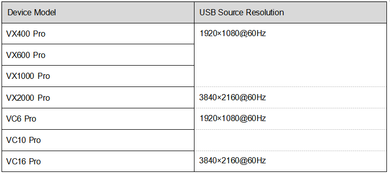
USB source properties
Play USB Files
The U-DISK connector on the front panel is inserted with a USB drive which is successfully identified.
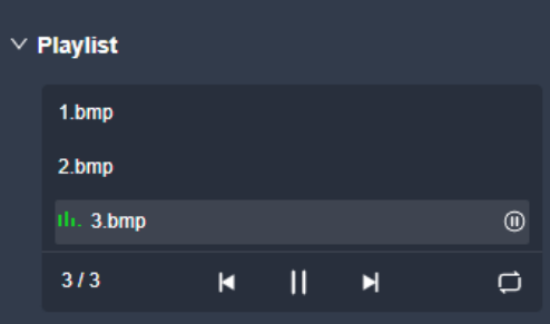
Play USB files
Configure Playback Parameters
Prerequisites: The U-DISK connector on the front panel is inserted with a USB drive which is successfully identified.
Notes
- Single-partition USB drive supported.
- File system: NTFS, FAT32 and exFAT.
- Max. width and height of media files: Width 3840 pixels, height 2160 pixels.
- Picture format: jpg, jpeg, png and bmp. Decoded image resolution: 3840×2160 or lower.
- Video format: mp4, mkv, mov, avi, flv, m4v, mpg, mpeg, ts.
- Video coding: H.264, H.265, MPEG-2, MPEG-4.
- Max. video frame rate: H.264: 3840×2160@30fps, H.265: 3840×2160@60fps, MPEG-2/MPEG-4: 1920×1080@60fps.
- Max. bitrate: H.264/H.265: 100Mbps, MPEG-2/MPEG-4: 50Mbps.
- Audio coding: AAC, AC3, DTS, MP3, DVD, DVD_LPCM, MP2, OPUS.
- Audio sampling rate: opus: 24kHz, 48kHz; Other formats: 22.05kHz to 94kHz.
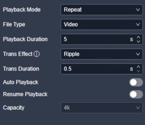
Playback parameters
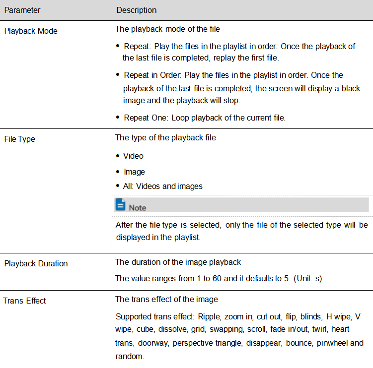
USB playback
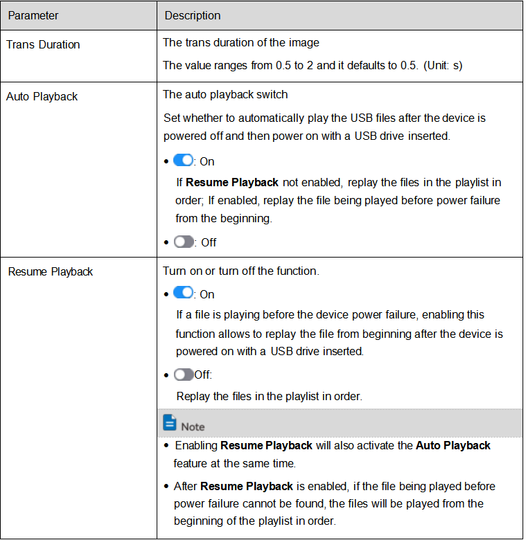
USB playback settings
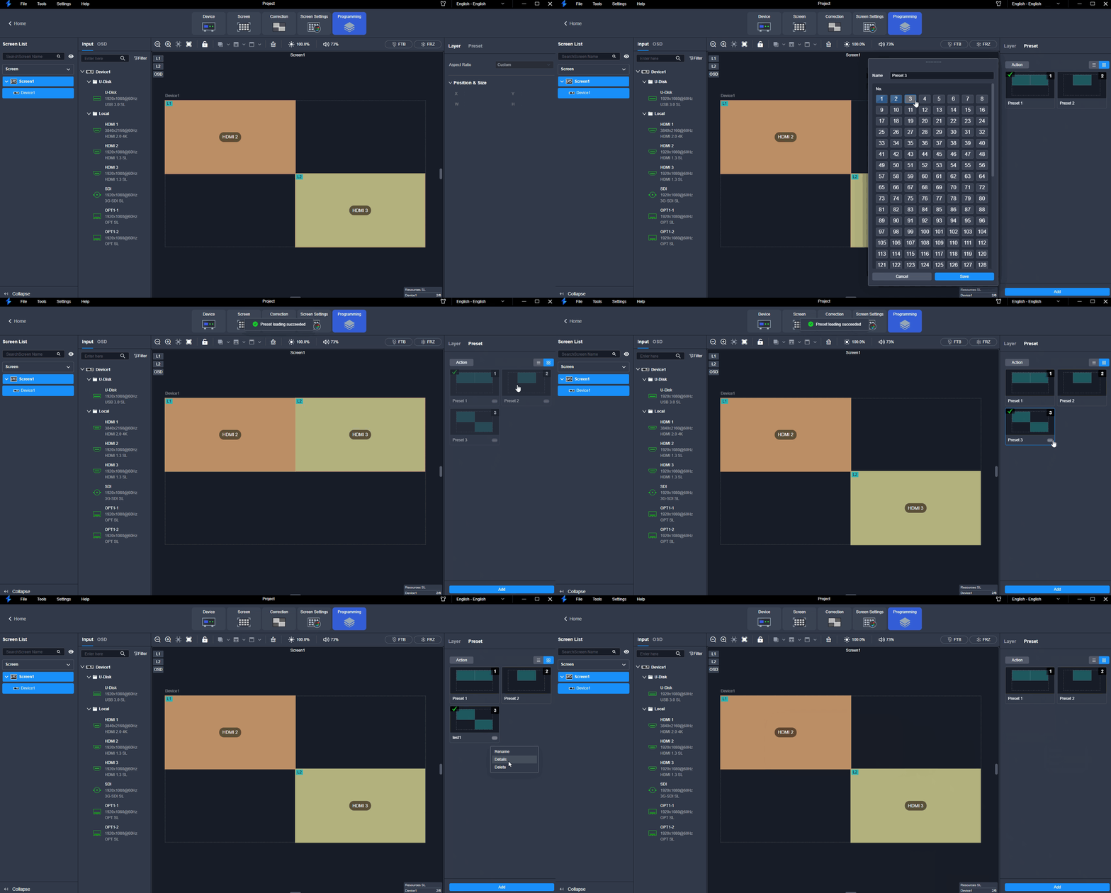
USB playback demo
Set Audio
Set Input Source Audio
On the Programming interface, click the Input tab to display the input source list. Hover the mouse over the desired input source and click the icon. In the popup menu, set the input source audio to Embedded Audio or Audio In.
Configure Layer Properties
Select the desired layer, and then set the layer-related properties in the property area on the right pane.
Configure Basic Properties
Configure the layer name, aspect ratio, position, size, as well as enabling the 3D effect.
⚠️ Note: After enabling the 3D function on the Screen Settings page, 3D switches of all the layers will be toggled on. If you want to use a 2D layer, please toggle off the 3D switch of the desired layer in the property area of the Programming page.
Crop Layer Sources
Prerequisites: A fine signal is connected to the input connector.
Notes
- The status and capacity of the cropped source remain consistent with the original one.
- The input cropping and 3D functions cannot be enabled at the same time.
Configure OSD
Both the text OSD and image OSD are supported.
Prerequisites: Before setting a time OSD or weather OSD, please ensure that the device is connected to the network to obtain the precise time and weather information.
Notes
- The OSD locates at the top and its priority cannot be adjusted.
- The text OSD and image OSD cannot be enabled together.
- The OSD function and remote control function cannot be enabled together.
Configure Text OSD
- Step 1: In the screen list on the left, select the desired screen.
- Step 2: Click the OSD tab.
- Step 3: Toggle the OSD switch to enable the OSD function.
Configure Image OSD
- Step 1: In the screen list on the left, select the desired screen.
- Step 2: Click the OSD tab.
- Step 3: Toggle the OSD switch to enable the OSD function.
Manage Presets
To manage the presets, click Preset on the right side of the Programming interface and perform the corresponding actions as needed.
Maintenance
In the menu bar, navigate to Tools > Maintain. Select the Device tab and the target devices, and then do the following as required.
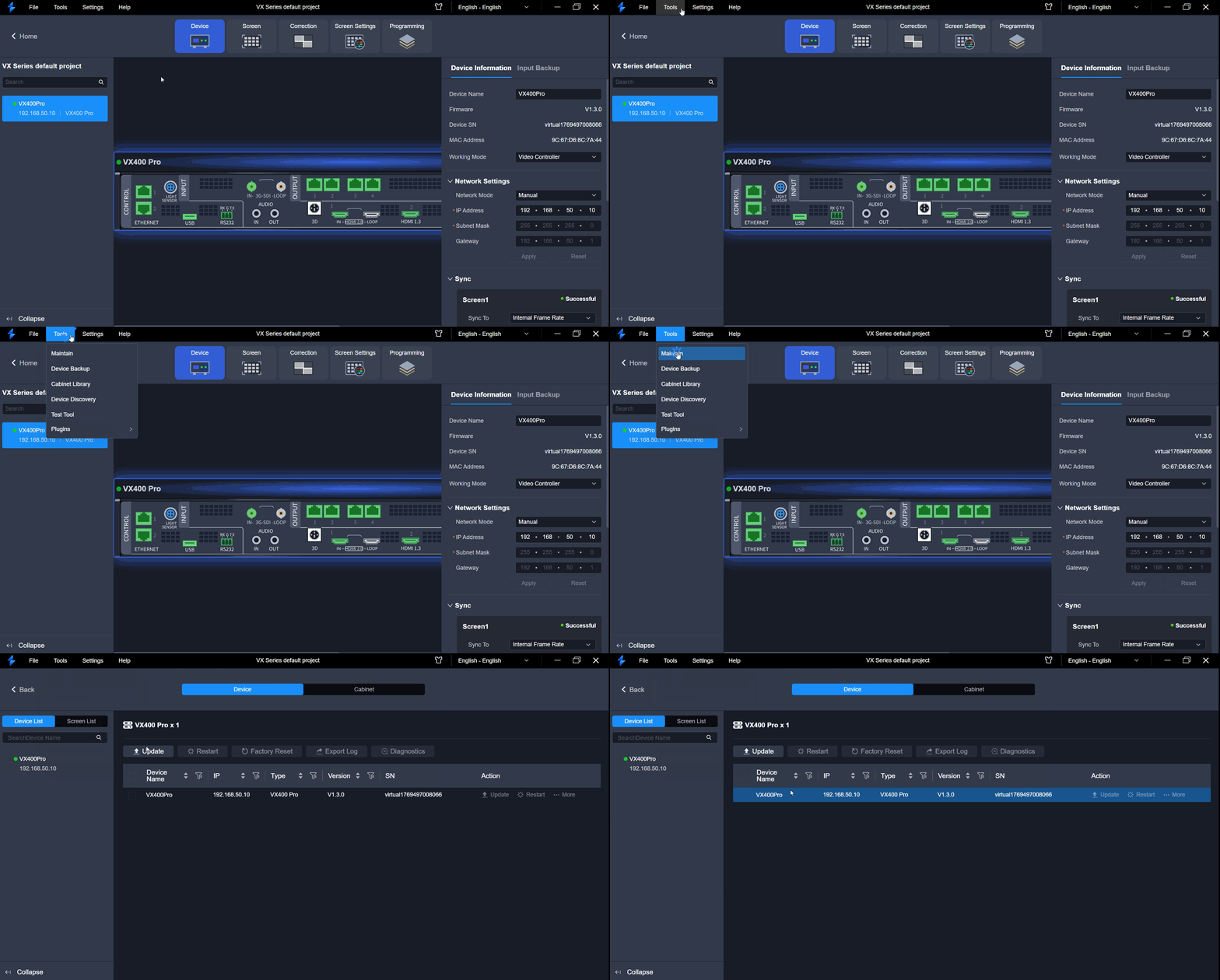
Maintenance
3. Additional features
3.1. Brightness Setting
The VX Pro series supports three ways to adjust the screen brightness.
Front Panel Knob (Screen Brightness)
- Press the knob to enter the main menu.
- Rotate to select Screen Brightness and press the knob.
- Rotate to adjust the brightness — the display shows the effect in real time.
- Press the knob to confirm. The brightness is applied and fixed to the receiving cards (parameters survive power-off).
Web (Brightness and Gamma)
- Go to Screen Adjustment > Adjust Image Quality > Adjust Brightness and Gamma.
- Brightness: 0% – 100%.
- Gamma: Enter a value manually.
- The Web also supports adjusting brightness and contrast per RGB channel.
Remote Control
- Short press the brightness keys: step adjustment.
- Long press: continuous fast adjustment.
⚠️ Note: When using an optical fiber transmission solution, make sure the optical modules and fiber types match (single-mode to single-mode, multi-mode to multi-mode), otherwise brightness adjustment may become ineffective.
3.2. Backup Setting
Configure Ethernet Port Backup
Test whether the pre-stored images, backup Ethernet ports and devices take effect without plugging and unplugging the Ethernet cables.
Prerequisites
- The pre-stored images, primary and backup Ethernet ports or primary and backup devices have been configured.
Set Dual RV Cards Backup
Receiving card backup allows you to set the backup relationship between two receiving cards. If the primary receiving card link fails, the backup one will take over the responsibilities of the primary receiving card and continue to work well to ensure the LED screen will not go black.
⚠️ Note: When you enable both the device backup and dual receiving cards backup, the former takes precedence over the latter. When the layer sources of two devices are disconnected, the device will switch to the backup receiving card link.
Configure Input Source Backup
Establish a backup relation for two input sources.
Input backup rules:
- In each backup group, two input sources serve as the backup for each other.
- The backup relation can only be established if the input connectors have identical capacities.
- The USB source supports the input backup settings.
- Each primary or backup source can have only one backup or primary source.
Restrictions on input backup functions:
Input sources A and B form a hot backup group. The current input source of the layer is input source A.
- Input A: No signal. Input B: Signal — The layer input source is switched to input B automatically. When input A resumes and input B still has a signal and Primary Source Preferred is not enabled, the layer input source will not be changed.
- Input A: No signal. Input B: Signal — The layer input source is switched to input B automatically. When input A resumes, but input B does not have a signal, the layer input source will be changed to input A.
- Input A: No signal. Input B: No signal — The layer input source will not be changed.
- Input A: Signal. Input B: No signal — If you manually switch the layer input source to input B, the source will automatically switch to input A.
Configure Device Backup
You can set one of the device as the primary device or the backup device. When the primary device has a problem or the primary device's Ethernet cable fails, the backup device will take over the responsibilities of the primary device seamlessly and continue to work well to ensure the LED screen will not go black.
Prerequisites
- Primary and backup devices must be on the same LAN.
- The models and device versions of the primary and backup devices must be the same.
Notes
- Three options to create a backup relation: NovaLCT, Unico or the device LCD menu. Choose only one method for setting up the backup relation. If you do mix them, you'll need to reset the device to factory settings and start over with just one method.
- In the device backup mode, the quantity of the cabinets loaded by each Ethernet port on both the primary and backup devices must be the same, but their data flow must be in a reversed way.
Operation Procedure
- Step 1: In the menu bar, go to Tools > Device Backup.
- Step 2: In the pop-up window, click Add to add a backup relation.
- Step 3: Select the primary and backup devices from the drop-down lists respectively.
- Step 4: Click OK to finish the backup relation settings.
3.3. Bright&Dark Line Adjustment
The bright/dark line adjustment is located in the Correction module of Unico. It manually fine-tunes the brightness at the seams between cabinets or modules to remove visible seams caused by splicing precision.
Adjust Bright/Dark Lines
Prerequisites: Cabinet configuration has been completed.
- Step 1: Select Correction at the top of the interface.
- Step 2: In the Bright/Dark Line tab of the property area, enable the Bright/Dark Line Correction switch.
- Receiving cards with an independent switch (A8s Pro, NV7508/7512/7516, DH7508-S/7512-S/7516-S, MRV208-NB7s): the switch must be on, otherwise adjustment is not available and tuned effects are not displayed.
- Other receiving cards: enabling Bright/Dark Line Correction or Brightness & Chromaticity Correction is sufficient.
- Step 3: Enable the correction switch and select Brightness Correction or Brightness & Chromaticity Correction (mutually exclusive).
- Step 4: Select the correction mode: Cabinet Seam (F1–F3) for seams between cabinets, Module Seam (F4–F6) for seams between modules.
- Step 5: (Optional) Override the module rows/columns if needed.
- Step 6: Set the display parameters and observe the effect. Shortcuts: W=white, R=red, G=green, B=blue.
- Step 7: Click or box-select the seams to correct in the topology area.
- Step 8: Set the adjustment parameters: Quick Adjustment (large step) or Fine Adjustment (small step).
- Step 9: Drag or scroll the mouse over the roller icon to adjust brightness; keyboard shortcut 1+Up/Down. Use Restore to Last Saved or Reset as needed.
- Step 10: Click Save when done.
Erase Bright/Dark Lines
When the cabinet specification changes (e.g. a receiving card is moved between cabinets or modules are replaced), previously adjusted bright/dark lines may be misplaced — erase and re-adjust.
- Step 1: Select the screen and enter Correction.
- Step 2: Switch the mode to Cabinet (F9).
- Step 3: Select the target cabinet and click Erase (auto-fixes after erasing).
⚠️ Note: Reading back full-screen correction coefficients may invalidate manually adjusted bright/dark lines — read back only the problem area locally.
3.4. Export/Import Projects
Project files are exported/imported in Unico from the device configuration interface.
Export Project
- Select the Online Project or Virtual Project tab and click Enter to open the device configuration interface.
- Select File > Export Project File from the menu bar.
- Check the data to export (Device Parameters and/or Resource Files).
- Click Export and choose the save path.
- Quick export: on the Online Project page, click Export next to the project list entry.
- Resource files include BKG, Logo, OSD, built-in sources, 3D LUT, etc.
- Virtual projects cannot be exported directly from the project list — enter the device configuration interface first.
Import Project
- Select the Online Project or Virtual Project tab and click Enter.
- Select File > Import Project File.
- Select a project file (.uprj format) and click Confirm.
- Choose the import target: Online Project or Virtual Project.
- After the device matches successfully, check the data to import and click OK.
- The software matches devices by SN, name, IP address, model and firmware version. You can adjust the match target manually.
- The device model must match the model in the project file.
- Virtual project files can be imported into online projects.
3.5. Device Discovery
Auto Discovery (Same Subnet)
When the control PC and the device are on the same LAN and subnet, Unico automatically scans and adds online devices of the same series to a default project. The online devices are listed under the Online Project tab with name, IP, model and online status. Double-click the device or click Enter to open the configuration interface.
Manual Search (Cross-Subnet / Restricted Network)
Devices on a different subnet are not auto-discovered. Use manual search:
- Select Tools > Device Search from the menu bar.
- Click Add in the Device Search window.
- Enter the target device IP and click OK.
⚠️ Note: If the device IP is changed to another subnet, it disappears from the auto-discovery list — use manual search instead.
UDP Protocol Search (Third-Party Control Integration)
| Parameter | Value |
|---|---|
| UDP port | 3800 |
| Search command | ASCII message rqProMI: |
| Target | Device IP or broadcast 255.255.255.255 |
| Response | Device replies with hex data containing rpProMI:App,0161 |
The local IPv4 must be on the same subnet as the VX device; add the port to the firewall allowlist; some network devices may block broadcast forwarding.
3.6. Export Logs
Via Device LCD Panel (USB Drive)
- Insert a USB drive into the USB 2.0 port on the rear panel.
- On the main menu, select System Settings > Log Export and press the knob.
- Rotate to select Apply and press the knob to confirm. The log file is exported to the root directory of the USB drive.
Clear any existing
log.zipon the USB drive before exporting to avoid mixing old and new logs.
Via Unico Web
VX Pro supports log export in Unico Web (browser access), not the desktop Unico software.
- In Chrome, allow the following permissions for the device IP site: pop-ups, automatic downloads, and insecure content.
- Enter the device IP in the browser to open Unico Web.
- Click Maintenance, select the target device, and click Log Export to save the device log locally.
Unico software logs: Select Settings > Log Export in the software, choose a save path, and click Save.
Device logs (from the device) and Unico software logs (from the control software) are two different types of logs. Chrome is the recommended browser.
3.7. 3D Setting
The VX Pro series supports 3D display through two solutions:
| Solution | Connection | Accessories |
|---|---|---|
| Traditional | Connect the device Ethernet port to an EMT200 Pro emitter | 3D glasses |
| New | Connect a third-party 3D emitter directly to the device's built-in 3D connector | 3D glasses |
3D Parameters
Go to Advanced Functions > 3D Settings on the device menu:
| Setting | Options / Range |
|---|---|
| Status | On / Off |
| Video source format | Side-by-Side, Top-and-Bottom, Frame Sequential |
| Eye priority | Left eye, Right eye |
| Enable third-party emitter | On / Off |
| Signal delay time | 0 – 20000 µs (default 7000, step 1) |
⚠️ Note:
- Enabling 3D with side-by-side or top-and-bottom sources halves the device output loading capacity — plan the wiring accordingly.
- HDR and 3D cannot be used at the same time.