Taurus Series
Device Configuration
Programs
1. Device Configuration
ViPlex Express is the desktop software used to configure Taurus media players, create playlists, publish schedules, and manage device status. For Taurus deployments, the normal workflow is to use Async Mode with a real device; Demo Mode can be used to practice the workflow without hardware.
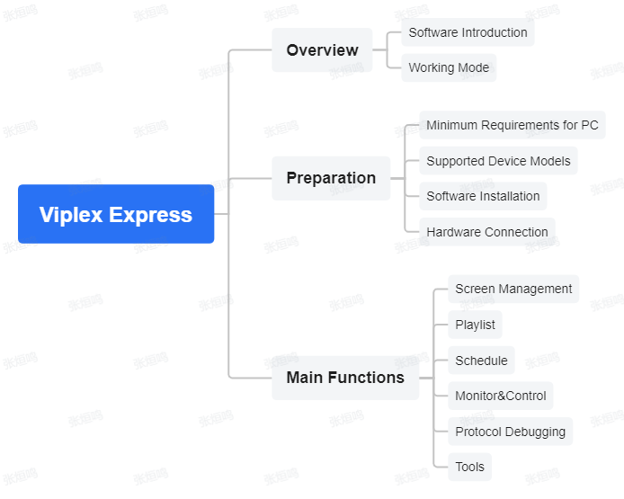
ViPlex Express
Before connecting a Taurus device in ViPlex Express, make sure the control computer meets the basic software requirements:
| Item | Minimum requirement |
|---|---|
| OS | Windows 10 64-bit |
| CPU | Intel i5 or equivalent |
| RAM | 4 GB |
| Storage | 60 GB |
| Graphics | Intel HD Graphics 4000 / comparable integrated GPU, or NVIDIA GeForce 8 series / AMD Radeon HD 5000 series and above |
| Video memory | 512 MB or more |
| OpenGL | 2.1 or later |
For Taurus-related TB devices, ViPlex Express 4.0 support depends on firmware version. Common supported models include TB10 Plus, TB20 Plus, TB30, TB40, TB50, TB60, TCC160, AD20, and LCB4K. If an older Taurus player is not recognized, upgrade it with ViPlex Express 3.0 first, then reconnect it in ViPlex Express 4.0.
To install the software, download the installer from the official NovaStar download center, run the installation package, and follow the setup wizard until completion. No special environment configuration is required.
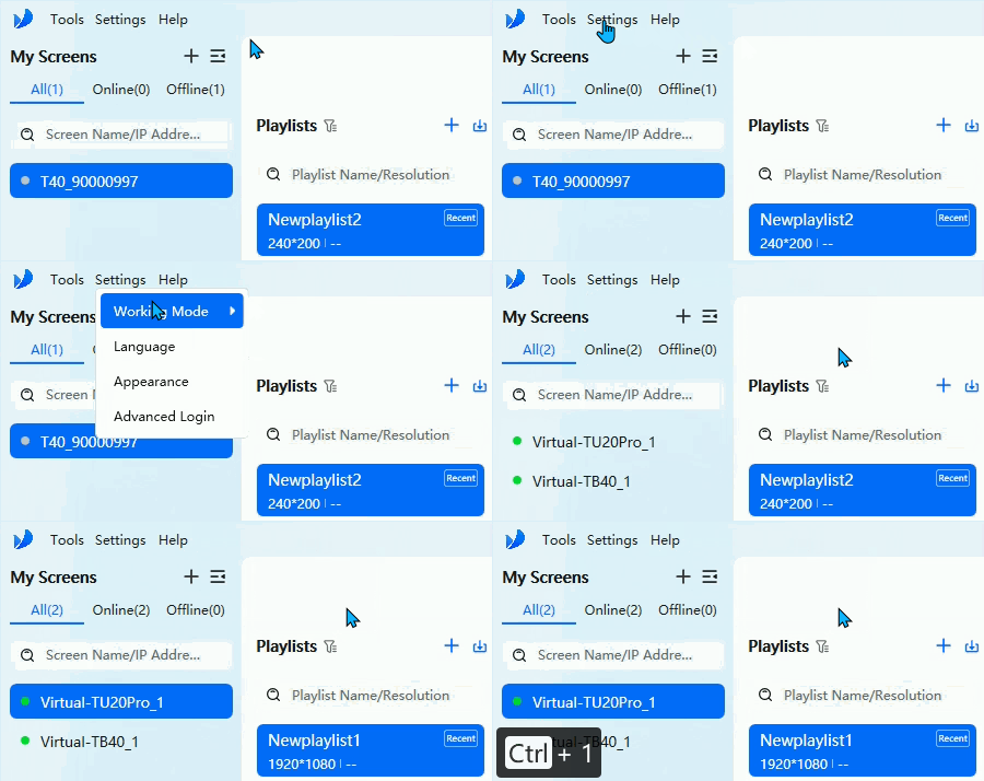
Working Mode
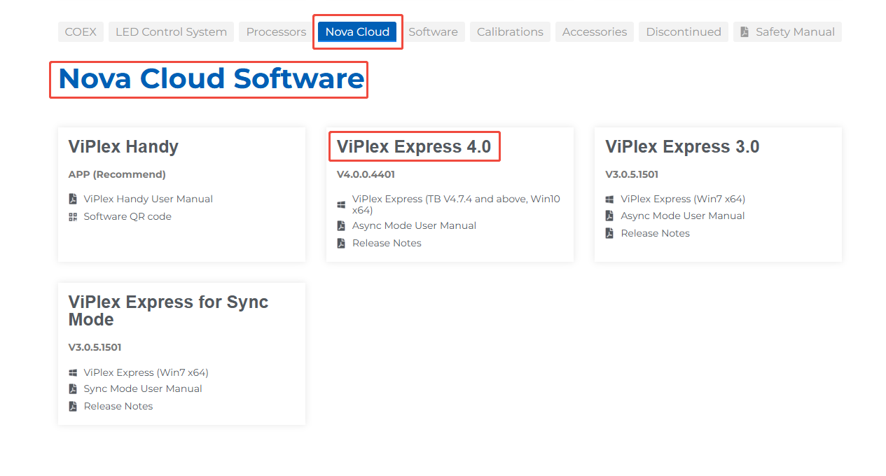
Download Link
1.1. Hardware Connection
ViPlex Express can connect to Taurus devices in three common ways:
- Ethernet direct connection
- Connect the computer directly to the Taurus player with an Ethernet cable.
- The factory default static IP is commonly
192.168.0.10, so the computer must be in the same subnet.
- Wi-Fi direct connection
- For Taurus devices with built-in Wi-Fi AP, connect the computer to the player SSID.
- The default SSID is usually model + last 8 digits of the SN, and the password is printed on the device label.
- LAN connection
- Connect the computer and Taurus player to the same router, either by wired Ethernet or the same Wi-Fi network.
- If the device uses a static IP, confirm both sides are in the same network segment.
If the device cannot be found over Ethernet, connect through Wi-Fi first to confirm the actual device IP.

Hardware Connection
1.2. Device Communication Setting
After the physical connection is ready, use ViPlex Express to discover and log in to the Taurus device.
Search and log in to the device
- The My Screens panel automatically searches nearby devices and separates them by All, Online, and Offline status.
- If the device is not found automatically, click Can’t find screen and search by IP Address or IP Address Range.
- Select an online Taurus device and log in with the connection password printed on the SSID label.
If screen search fails:
- Confirm the device is powered on.
- Confirm the Wi-Fi antenna is installed when required.
- Make sure the computer and the Taurus device are on the same local network.
- Disable VPN and check firewall settings on the control computer.
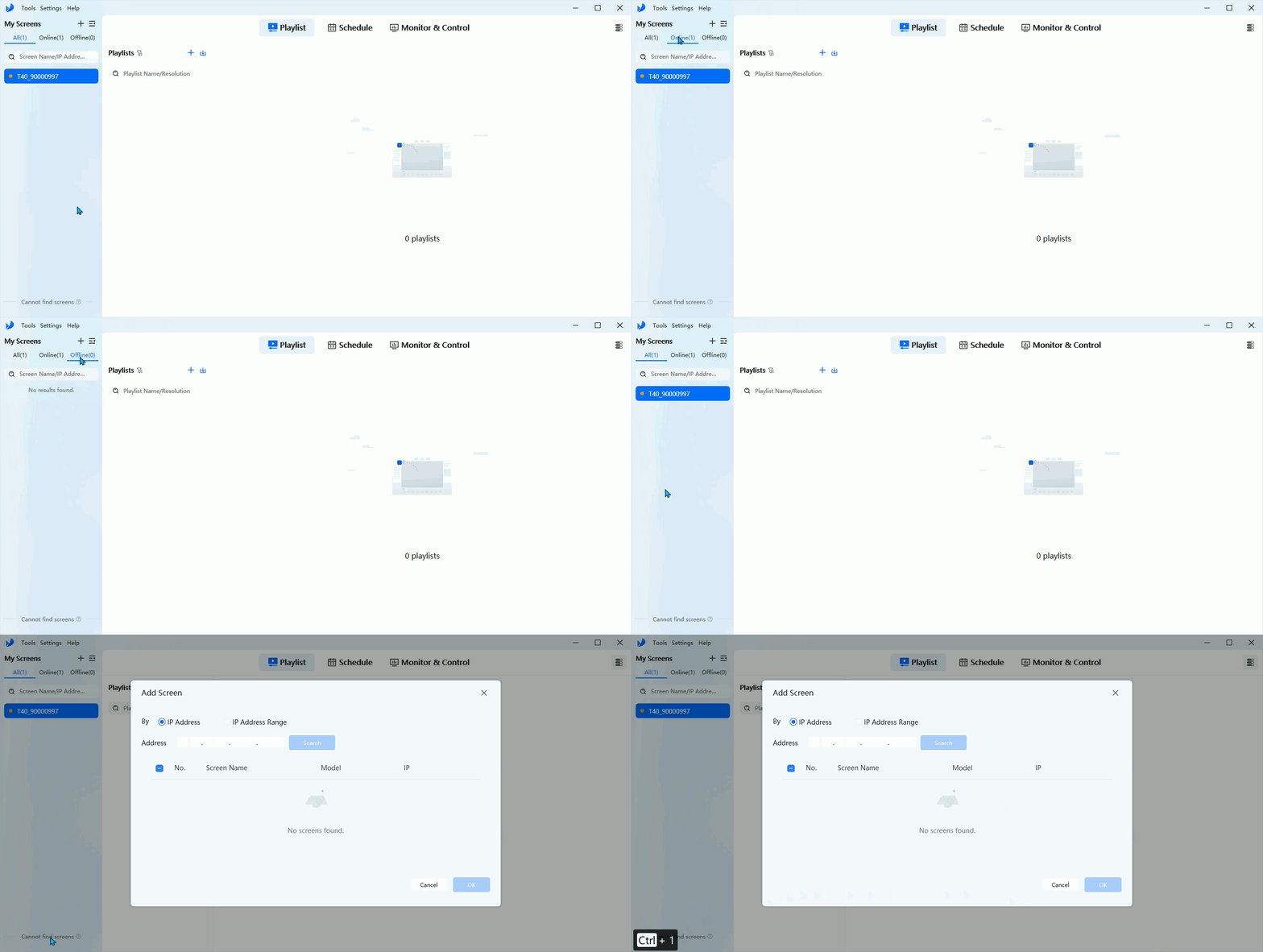
Search Screens
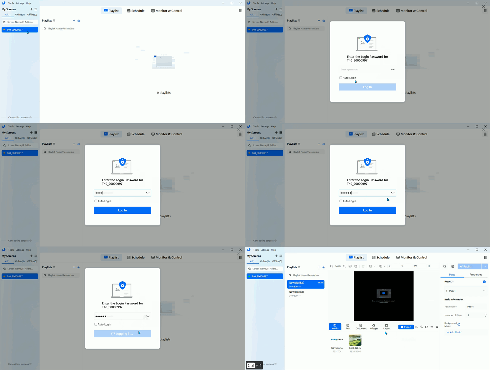
Log in to the Screen
Screen grouping
- Click the + button to create a group.
- Right-click a group to rename it, create sub-groups, or disband it.
- Drag screens or groups manually to adjust order or merge them.
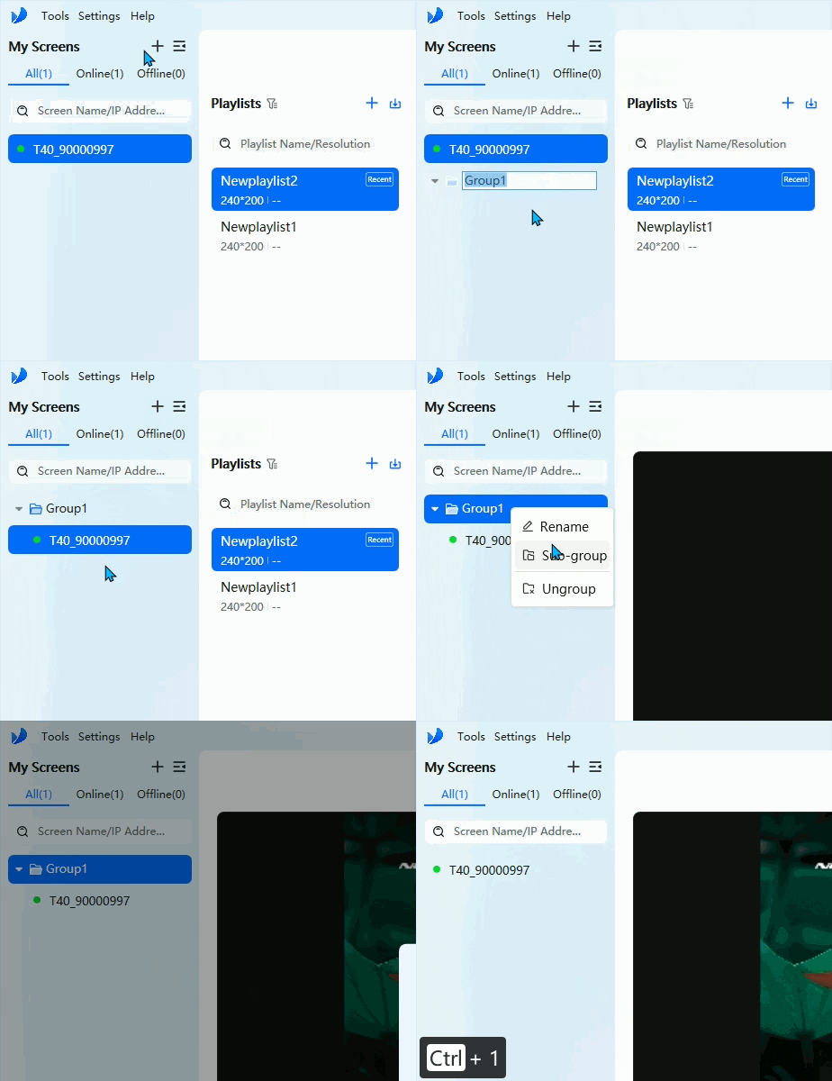
Screen Group
Network settings
ViPlex Express can also configure how Taurus connects to the network:
- Wired network for LAN access
- Wi-Fi by scanning nearby networks or manually entering SSID, password, and encryption
- AP mode to modify the device Wi-Fi AP name and password
The 4G network options in the original ViPlex Express guide apply only to specific TB and JT hardware combinations and depend on the corresponding network module and SIM card.
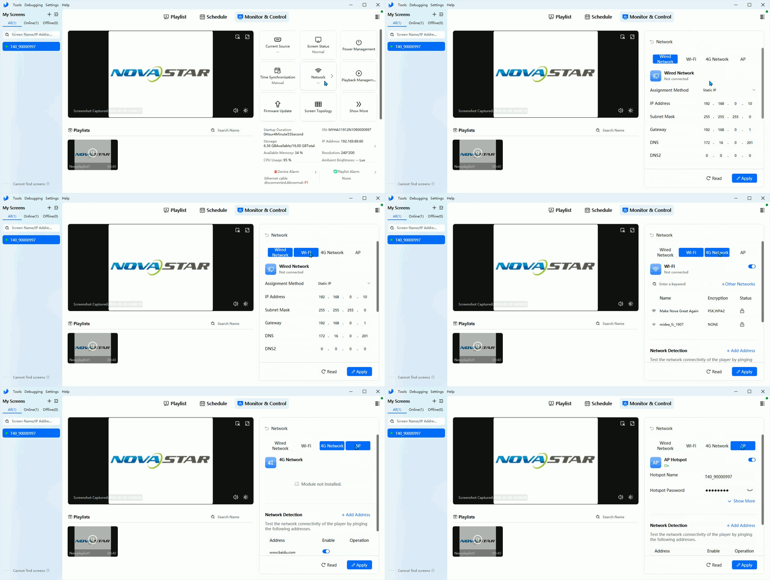
Network Settings
1.3. Taurus Firmware Upgrade
Use firmware upgrade when the Taurus player needs a new version or when ViPlex Express 4.0 cannot recognize an older device.
Precautions
- Do not power off the device during upgrade.
- If the Taurus player version is lower than V2.3.0, upgrade it to V2.3.0 first through a local package before upgrading to V3.0.0 or later.
Version transition and compatibility details
- Transition version by hardware platform: For the 3128/3368 platform, use V2.3.0 as the transition version; for the 3566 platform, use V3.7.
- Cross-major-version upgrades (e.g. 1.x to 4.x) must use the intermediate version, otherwise the database structure change can cause playlist loss (usually only recoverable by restoring factory settings).
- APP package vs OS package: Custom firmware may be delivered as an APP package (application layer only, no underlying OS). The underlying OS version must match before upgrading an APP package, otherwise high-version ViPlex Express compatibility checks fail (e.g. V3.0.5.1501 reports "login failed" — downgrade ViPlex Express to V2.27.0 or upgrade the full OS package first).
- Cloud platform minimum firmware versions: VNNOX (overseas cloud) requires firmware V2.4.0 or later; ViPlex cloud / ScreenBoss requires later than V3.3.0 (and the screen must not be bound).
- Hikvision CTM customized versions: Upgrading within the CTM version is fine; upgrading between the general version and the CTM version is strictly forbidden. Devices shipped with a version lower than V4.1.0 only support the Hikvision customized firmware.
- Downgrade note: Local downgrade clears the database, keeping only the screen configuration and IP parameters.
Online upgrade
- Open Tools > Firmware Update > Online Upgrade.
- Click Refresh.
- Select the Taurus device to upgrade.
- Click Upgrade.
Local upgrade
- Open Tools > Firmware Update > Local Upgrade.
- Select the local firmware package.
- Click Refresh.
- Start the upgrade.
Local downgrade
- Go to Settings > Advanced Login.
- Enter the hidden code:
selftest/666888/novasoft. - Open Tools > Firmware Update > Local Downgrade.
- Select the local firmware package and complete the downgrade.
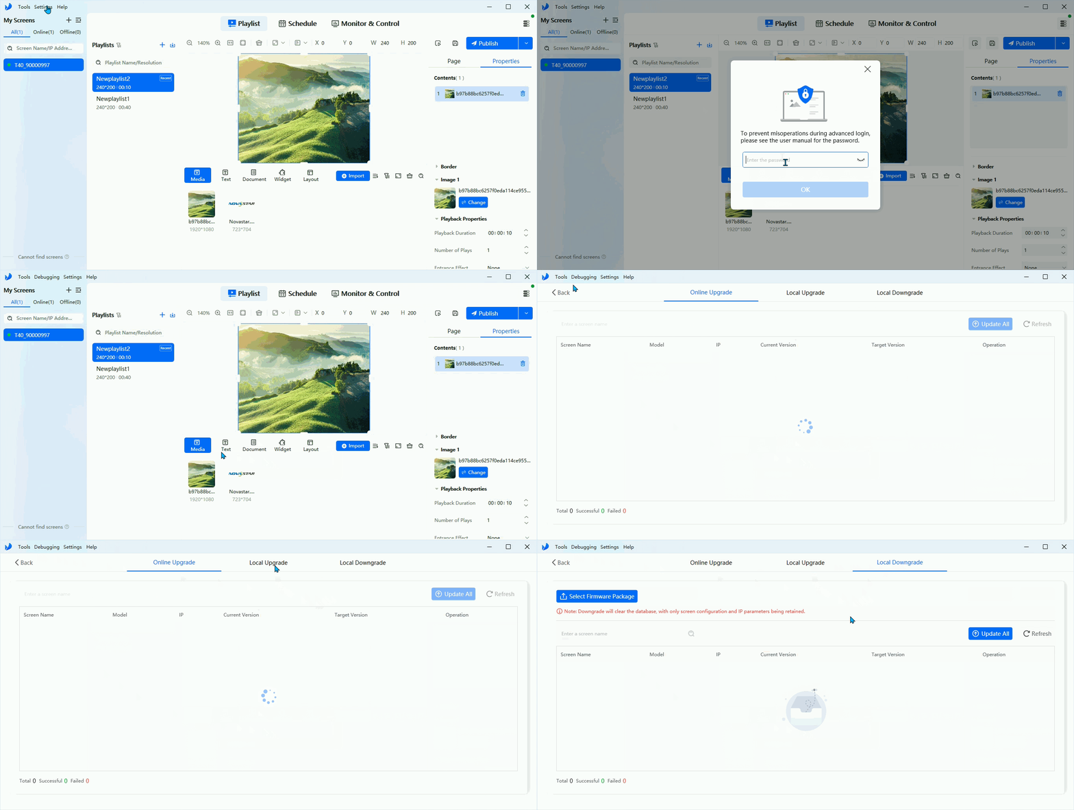
Device Upgrade
1.4. Cabinet Configuration
For Taurus projects that need basic receiving-card topology setup, ViPlex Express provides Screen Topology without requiring NovaLCT for the initial logical connection.
Basic topology setup
- Enter the hidden code:
selftest/666888/novasoft. - Open the screen topology page.
- Set the number of columns and rows of receiving cards on the right side.
- Complete the logical cabinet arrangement and connection.
This workflow is suitable for standard screens and for selected ultra-wide screen scenarios.
Taurus-specific note
- Among Taurus-class devices, TB60 supports ultra-wide screen configuration in ViPlex Express.
- For playlists up to 16368 pixels wide on TB60, ViPlex Express can be used directly.
- For wider special projects, NovaStar technical guidance is still required.
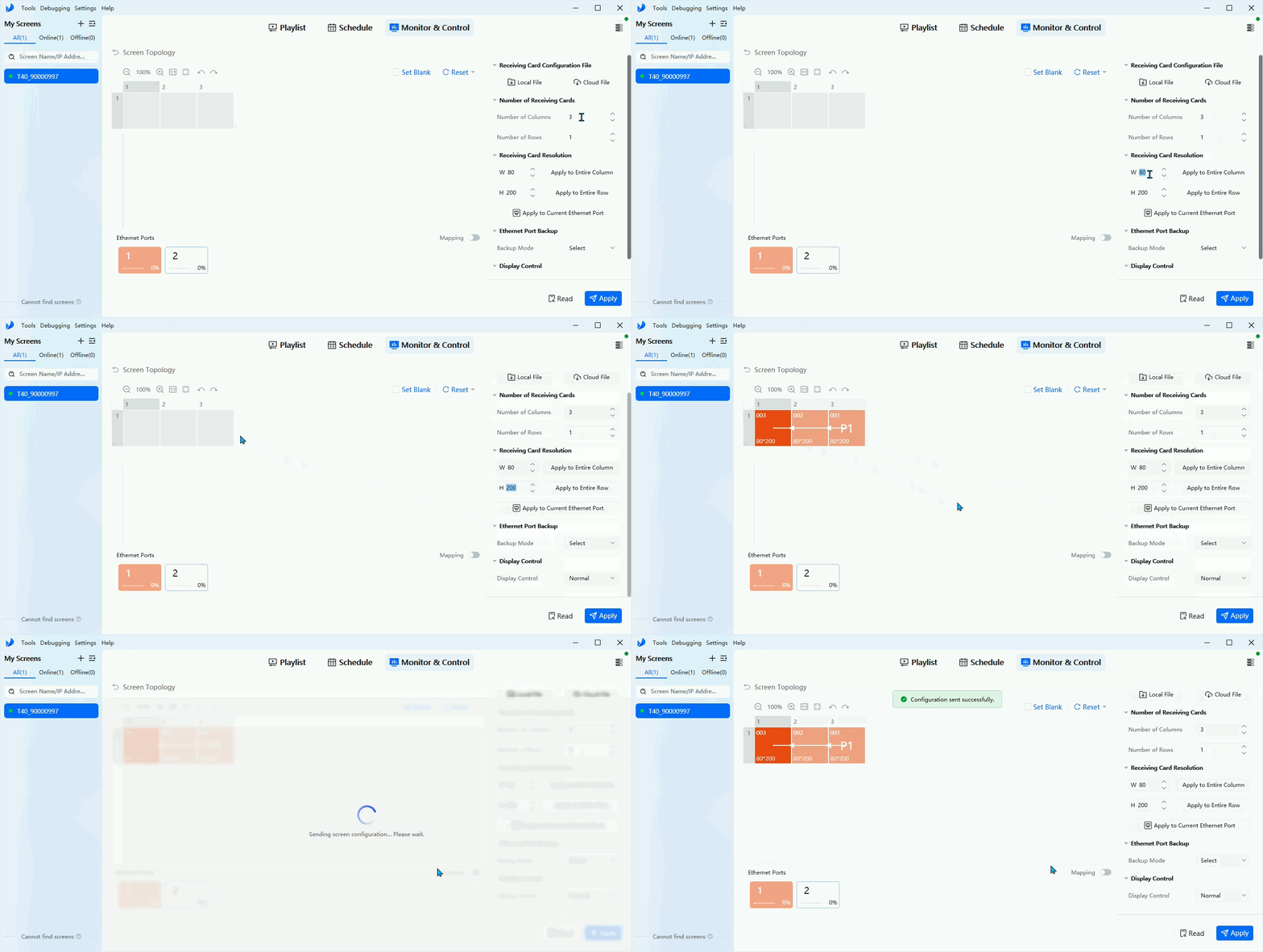
Screen Topology
1.5. Screen Configuration
ViPlex Express can configure the main screen parameters that affect how Taurus outputs content.
Source control mode
- Manual: switch freely between internal source and HDMI source
- Scheduled: switch source according to a time plan
- HDMI Preferred: prioritize HDMI input when it is available
Internal source resolution
- Click Internal Source Resolution Configuration.
- Set the output resolution and frame rate.
- Click OK.
The configured resolution refers to the Taurus operating system output resolution and should be greater than the actual screen resolution.
Input source EDID and scaling
- Use Input Source EDID Configuration to set EDID and frame rate for the input source.
- Scaling is optional. On Taurus devices, only the HDMI source supports scaling.
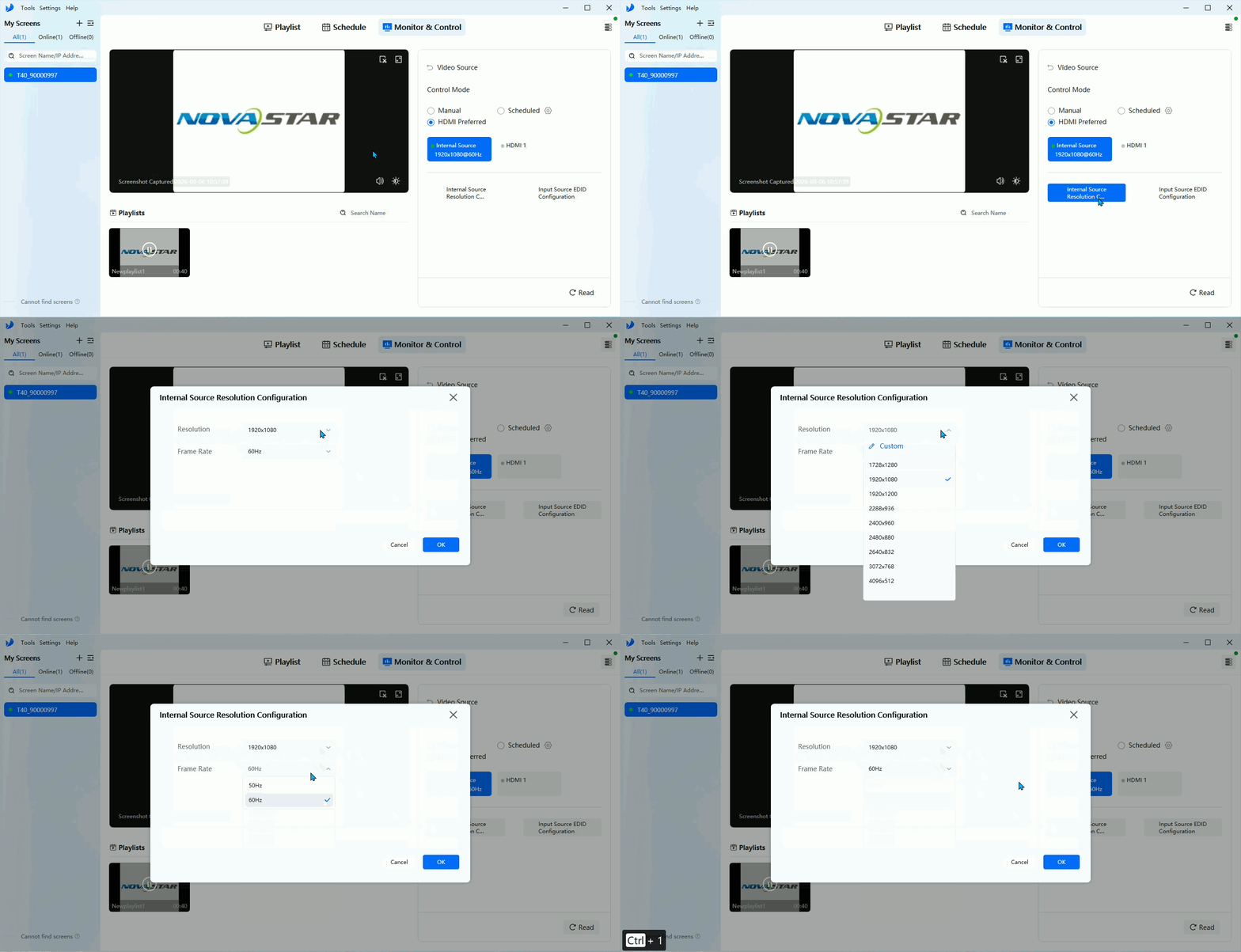
Internal Source Resolution
2. Programs
ViPlex Express manages published content through playlists and schedules. A playlist defines what to play, and a schedule defines when to play it.
2.1. Playlist
Create, import, and read back playlists
- Select the target Taurus screen in My Screens and click Playlist.
- Click the + icon next to Playlists to create a new playlist.
- Use the filter icon to display playlists matching the current resolution or other resolutions.
- Right-click a playlist to rename, copy, export, or delete it.
- Click the download icon next to Playlists to:
- Import from Computer
- Read from Player for locally stored playlists
Cloud playlists are not supported for readback.
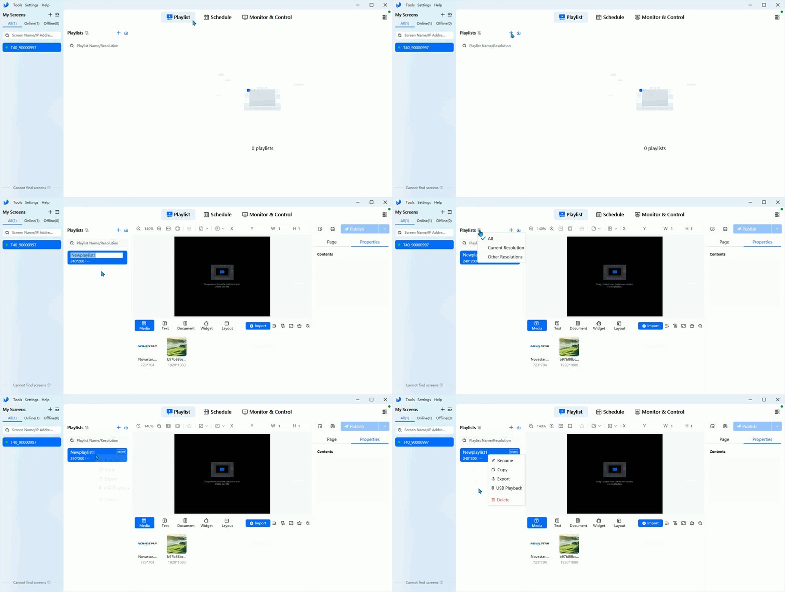
Create Playlist
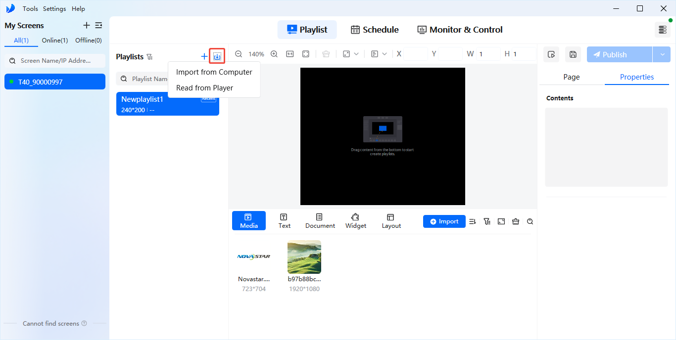
Import Playlist
Edit playlist pages and media
- In the Pages panel, add, copy, delete, or reorder pages.
- Set page name and playback count as needed.
- Add media such as videos, images, text, documents, weather, clocks, webpages, and streaming content.
- Drag local files into the media library or use Import Media.
- After placing content on the canvas, adjust position and size from the top toolbar and fine-tune duration and other properties from the right-side panel.
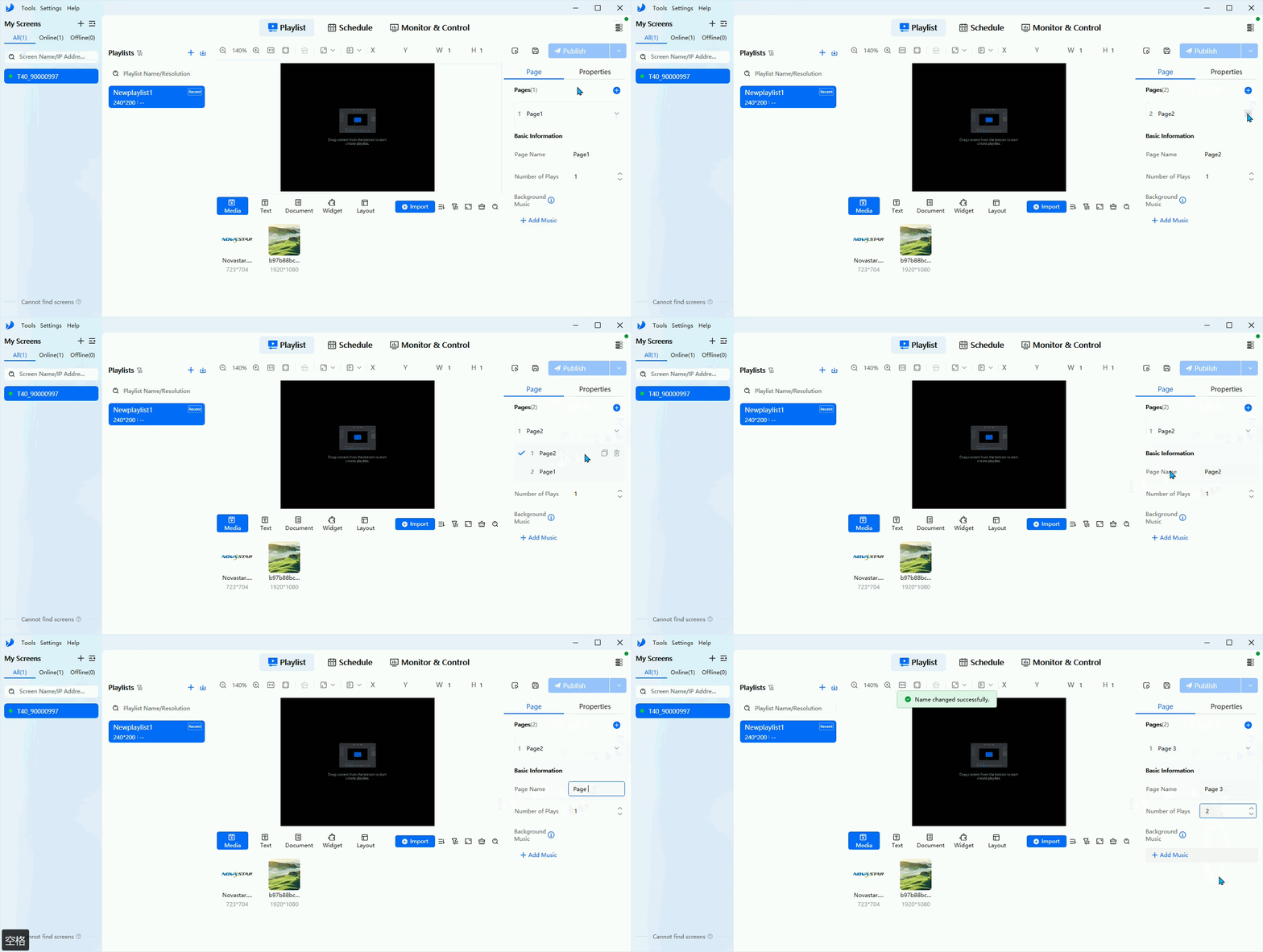
Add Playlist Pages
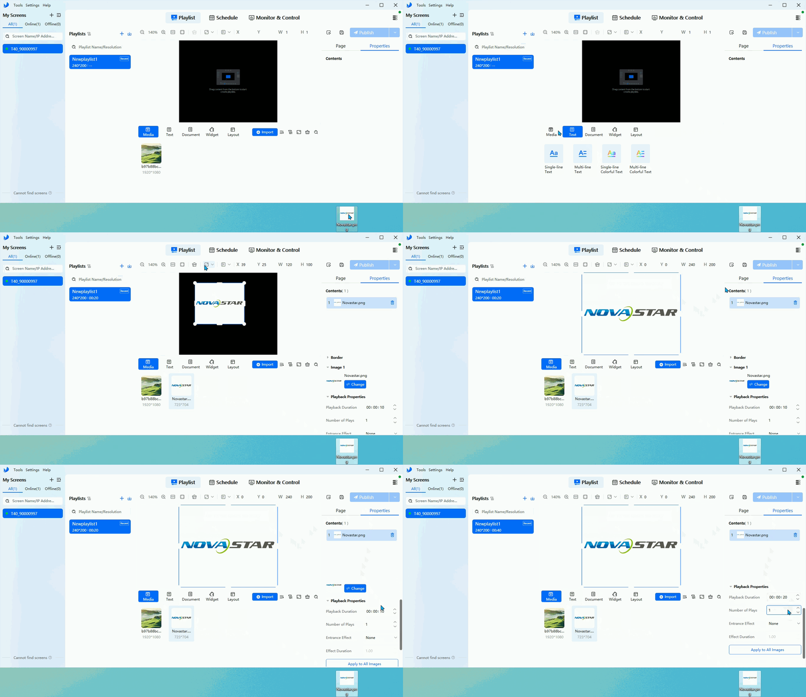
Add Media
Usage notes
- For Excel import, use the default row height where possible.
- The number of rows should be 600 or less.
- The column width should not exceed the width of a horizontal A4 page.
- Embedded images and custom numeric cell formats are not supported.
- Weather, webpage, and streaming media require valid URLs, and weather also requires internet connectivity on the screen side.
Preview and publish
- Click Save after editing.
- Use Preview first if needed, and press
Escto exit preview. - Click Publish and choose:
- Single Publish
- Batch Publish
Make sure the playlist resolution matches the actual screen resolution. Blank pages cannot be published.
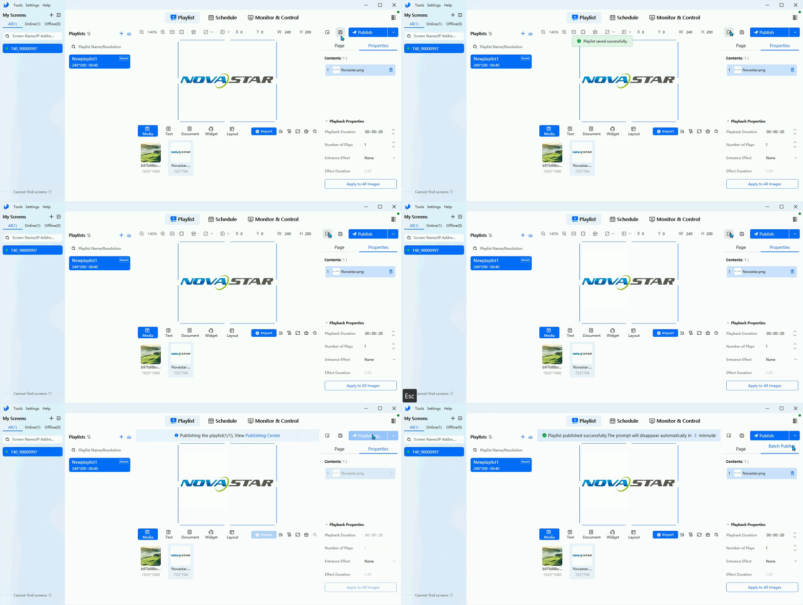
Publish Playlist
USB playback
If the Taurus player supports USB import:
- Right-click the playlist and choose USB Playback.
- Select a playback mode:
- Plug-and-play: starts immediately when the USB drive is inserted
- Copy-and-play: copies the playlist into player storage before playback
- Select the USB save path.
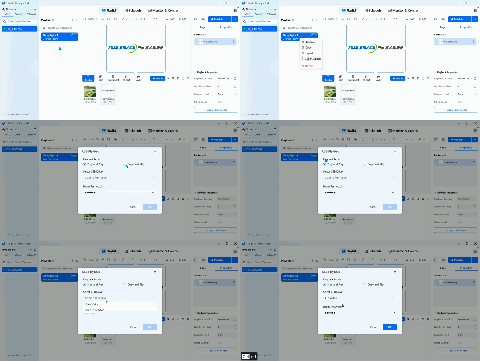
USB Playback
2.2. Schedule
Create a schedule
- Open Schedule.
- Click the + icon next to the schedule list to create a new schedule.
- Right-click a schedule to rename, copy, export, or delete it.
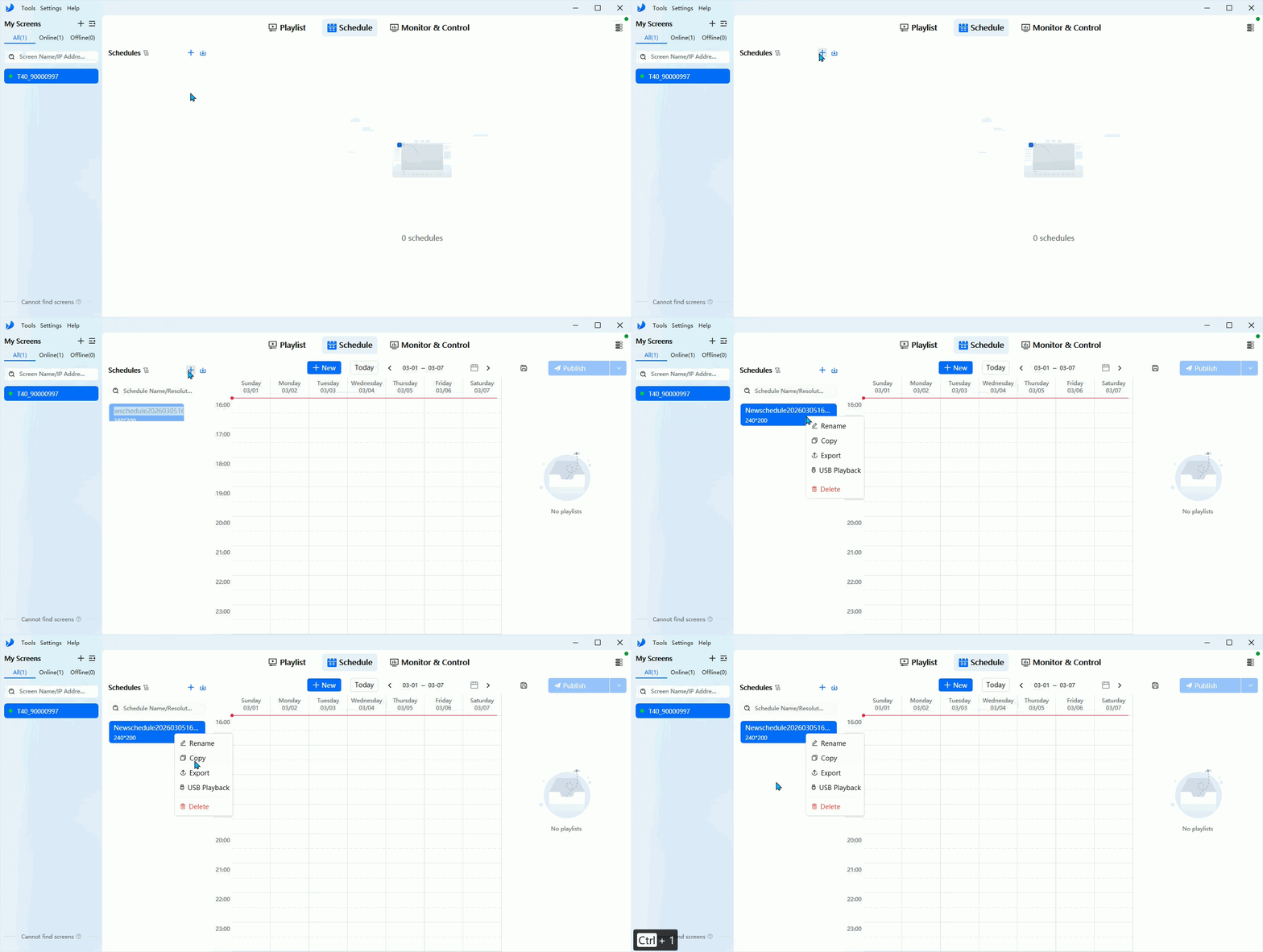
Create Schedule
Add tasks
- Click a blank area in the calendar.
- Choose the playlist to play.
- Set repeat mode, playback date, start time, and end time.
- Click OK.
If multiple playlists overlap in the same time range, only the leftmost playlist is played.
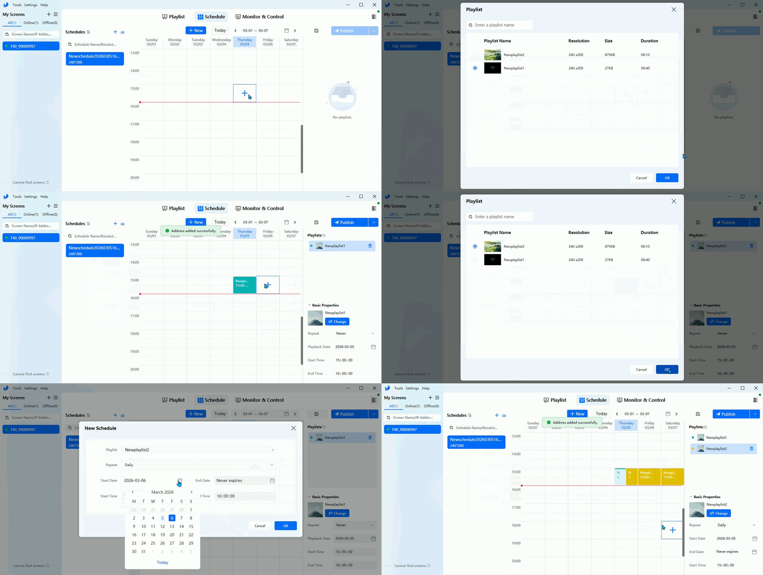
Add Schedule Tasks
Publish the schedule
- Click Save after editing.
- Click Publish.
- Choose Single Publish or Batch Publish.
3. Monitor & Control
After the Taurus device is online, ViPlex Express can be used to monitor device status and control playback-related settings.
3.1. Current Source
- Control Mode
- Manual: You can freely switch between the internal source and the HDMI source.
- Scheduled: Switch between the internal source and the HDMI source according to a time schedule.
- HDMI Preferred: The device prioritizes the HDMI input as the video source.
- Internal Source Resolution Configuration
- Steps: Click Internal Source Resolution Configuration, set the resolution and frame rate in the pop-up window, then click OK.
⚠️ Note:
- The resolution refers to the output resolution of the Taurus player operating system.
- This resolution must be greater than the actual screen resolution.
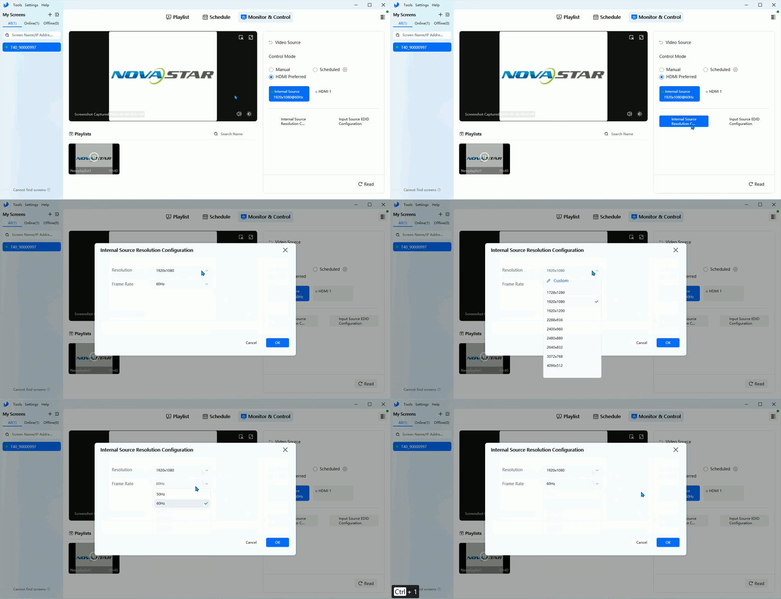
Current Source
- Input Source EDID Configuration
- Steps: Click Input Source EDID Configuration, then set the EDID and frame rate in the pop-up window.
- Scaling (Optional)
- Currently, scaling can only be enabled or disabled; setting a specific scaled resolution is not supported.
- TU series devices: both the internal source and the HDMI source support scaling.
- Taurus series devices: only the HDMI source supports scaling.
3.2. Screen Status
- Switch between Normal Display and Black Screen
- Manual mode changes immediately
- Scheduled mode changes according to time settings
- Adjust brightness
- Manual by slider or direct value entry
- Scheduled by time-based brightness values
- Automatic with a light sensor and brightness mapping table
- Adjust color temperature
- Warm, Standard, or Cool
- Adjust volume for playlist playback
Black Screen does not mean the power is off.
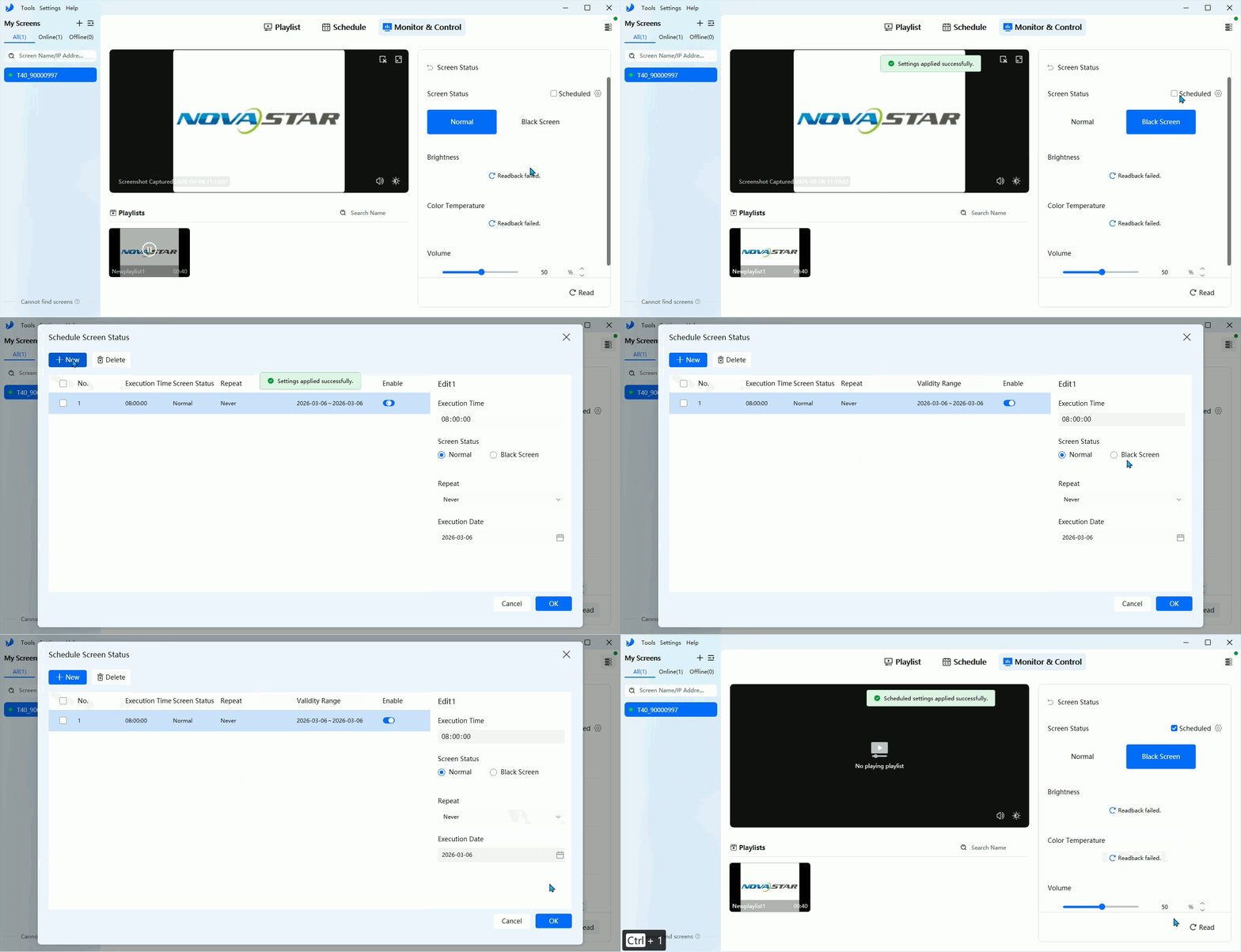
Screen Status
3.3. Power Management
- Use relay-based power management when supported.
- Screen Power
- Manual: click Start or Stop
- Scheduled: define automatic power cycles
- Restart Configuration
- Restart Now for immediate restart
- Scheduled Restart for periodic maintenance
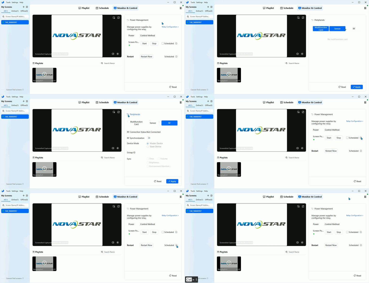
Power Management
3.4. Time Synchronization
To keep playback synchronized across devices, configure:
- Manual time setting for time zone and local time
- Automatic synchronization
- NTP sync, recommended for most projects
- GPS sync when a GPS module is installed
- RF sync when RF modules and master/slave timing are used
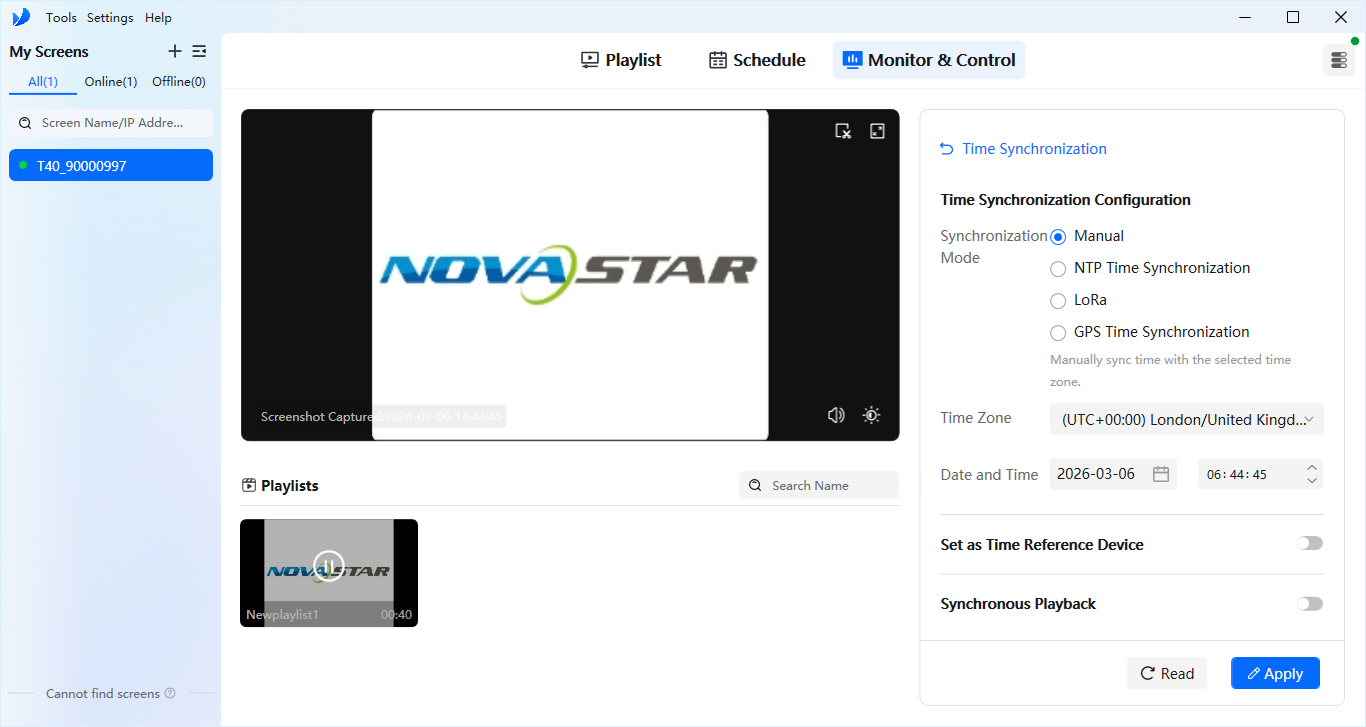
Time Synchronization
3.5. Network Configuration
ViPlex Express can configure how Taurus connects to the network:
- Wired Network for LAN access.
- Wi-Fi: Turn on the Wi-Fi switch, search for nearby Wi-Fi networks, select the one to connect to, and enter the password. You can also click Other Networks to manually enter the SSID, password, and encryption method.
- 4G Network: Only TB and JT series devices support 4G network configuration. Install a network module and a 4G SIM card.
- AP mode: Modify the device's Wi-Fi AP name, password, and other related settings.
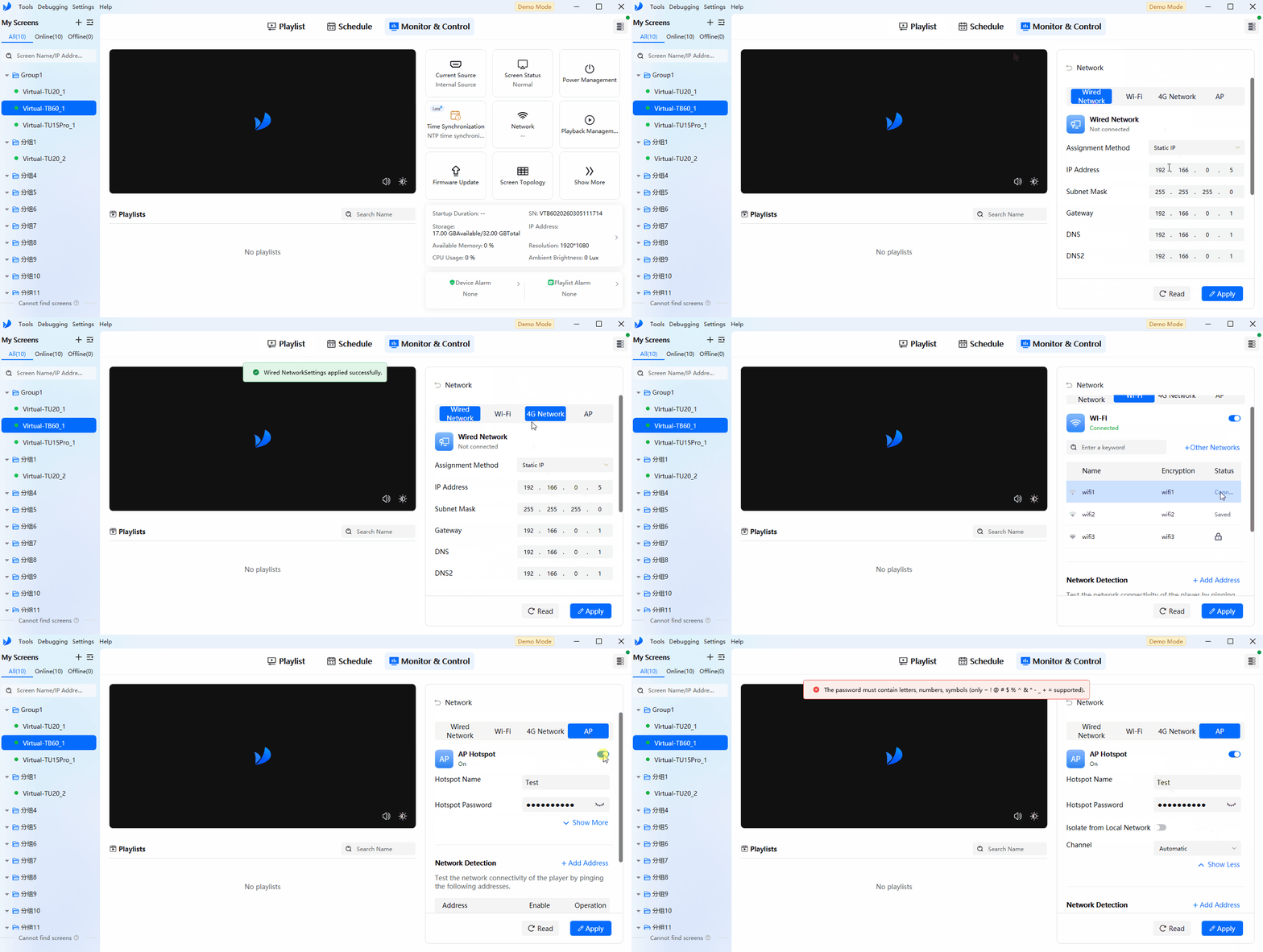
Network Configuration
3.6. Playback Management
Playback Management includes:
- Viewing storage information and managing playlists on the device
- Playback configuration such as:
- Preset Image
- Startup Logo
- No Internet Image for supported Taurus firmware
- Simple USB Playback
- Multi-Screen Mosaic on supported devices and firmware versions
For simple USB playback, store image and video files in the USB root directory and name them in ascending three-digit order, such as 001-xxx, 002-xxx, and so on.
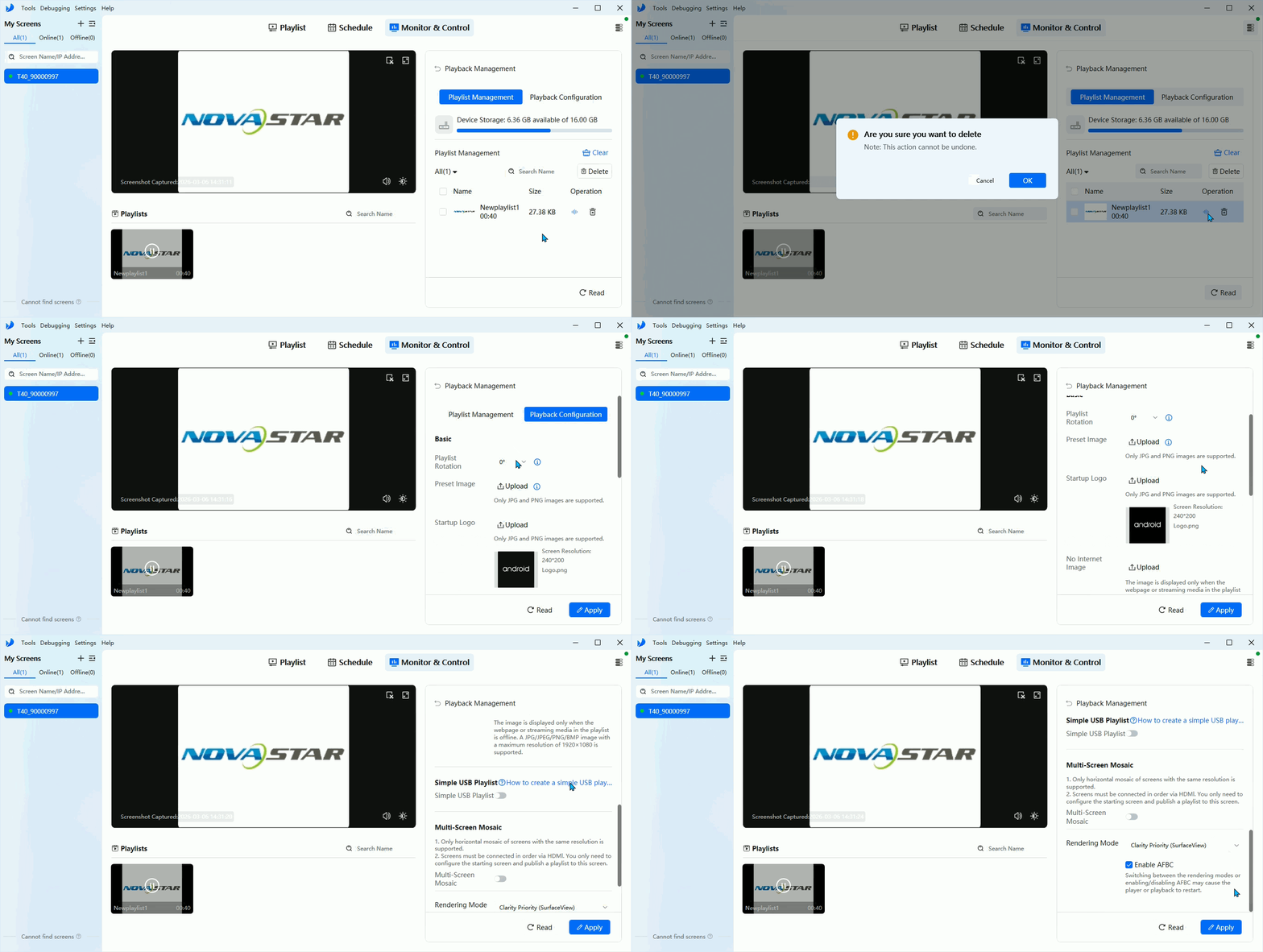
Playback Management
3.7. Cloud Server
Bind the Taurus device to the Vnnox Media platform to support remote content creation and remote publishing. The server node and authentication credentials in ViPlex Express must match the Vnnox Media account settings.
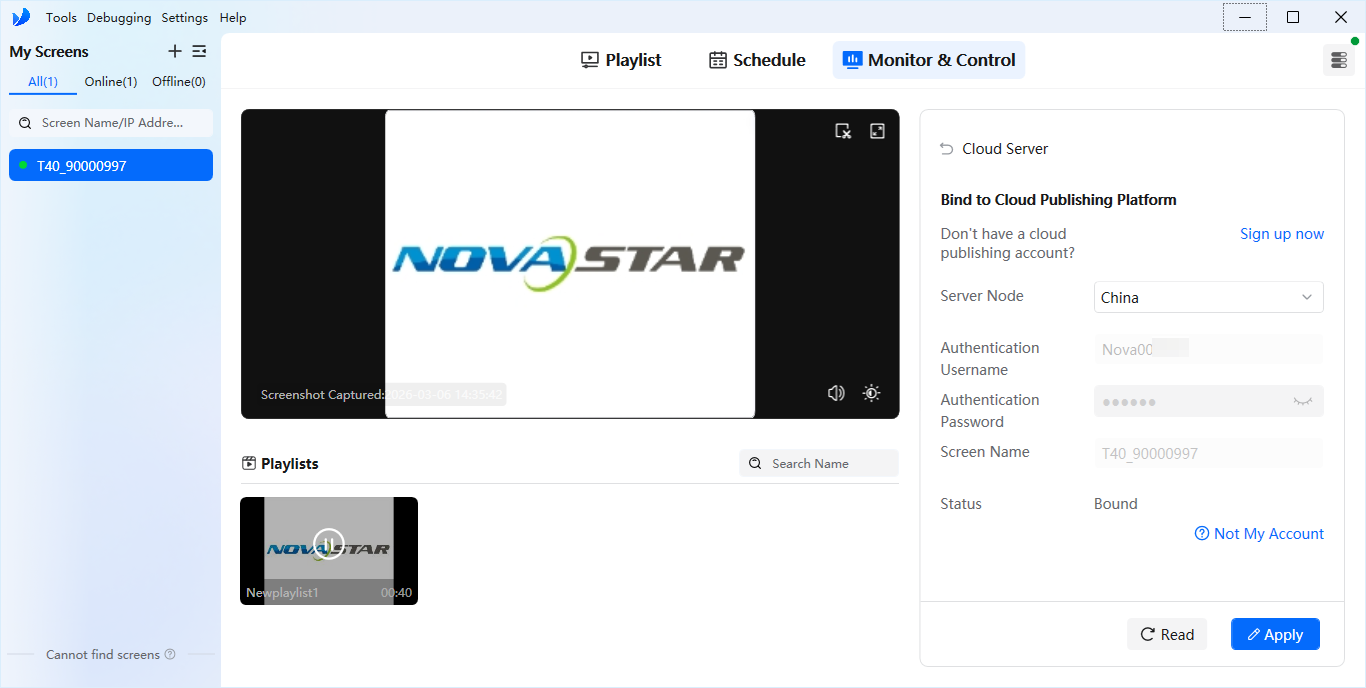
Cloud Server
3.8. Peripherals
- Manage connected peripherals such as sensors and RF modules
- Configure sensor-related features after physical connection
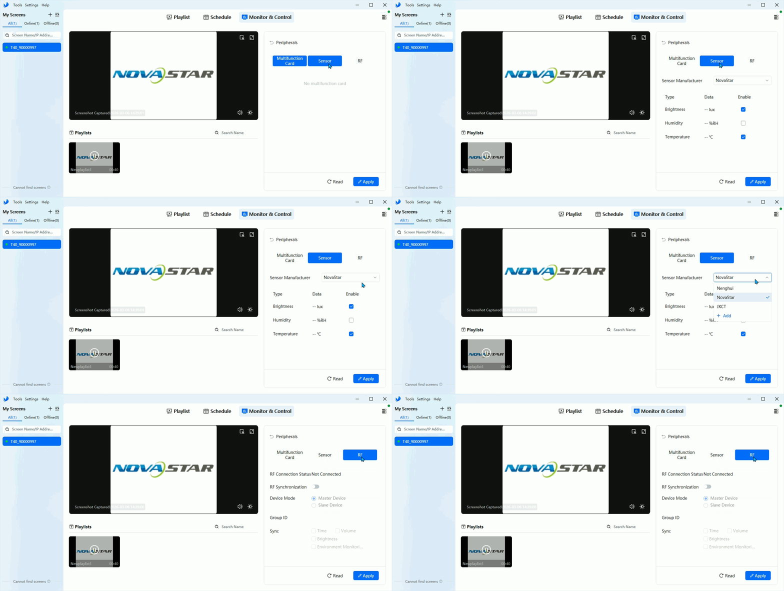
Peripherals
Advanced tools and software settings
ViPlex Express also provides several maintenance and software-side utilities:
- Debugging Tool
- collect device and control-computer logs
- manage files
- enable or disable channels such as ADB
- install third-party APKs when required
- run SSH commands for debugging
- Working Mode
- Async Mode for real Taurus publishing
- Demo Mode for virtual-device training and demonstration
- Language and Appearance settings
- Check for Updates for the desktop software itself
- User Manual entry for the official full documentation
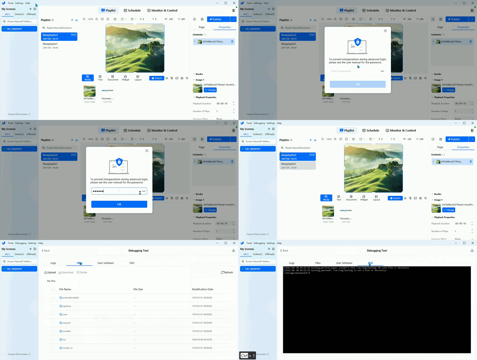
Debugging Tool
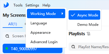
Working Mode
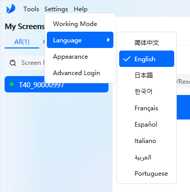
Language
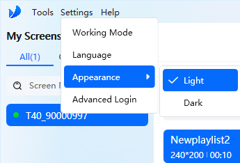
Appearance
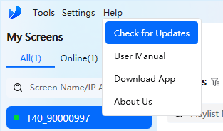
Check for Updates
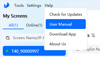
User Manual
3.9. About the Screen
Check About the screen to view SN, firmware version, and network information.
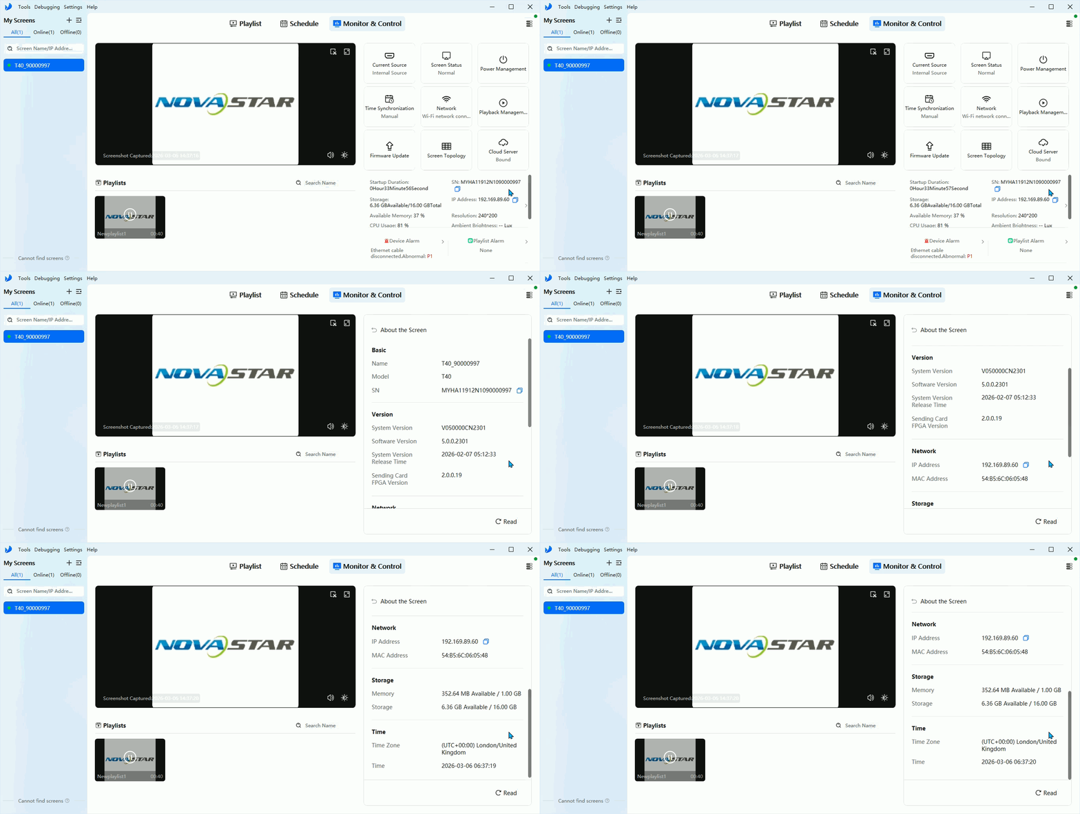
About the Screen
3.10. Taurus Version Compatibility
Devices of specific models and firmware versions can use ViPlex Express 4.0.
| Series | Firmware Version | Models |
|---|---|---|
| JT | V1.15.0 and later | JT50 Plus/JT200 |
| TU | V1.6.0 and later | TU15 Pro/TU20 Pro/TU4K Pro |
| TB | V5.0.0 and later | TB10 Plus/TB20 Plus/TCC160 TB30/TB40/TB50/TB60/J series /AD20/LCB4K |
| TB | V4.7.4.1801 | TB10 Plus/TB20 Plus/TCC160 TB30/TB40/TB50/TB60/AD20/LCB4K TB1-4G/TB2-4G |
⚠️ Note: Please upgrade your device using ViPlex Express 3.0 first. Only after that will ViPlex Express 4.0 be able to recognize your device.
3.11. Accessory Installation
3.11.1. Multifunction Card
Configure Multifunction Card in NovaLCT.
Multifunction Card
- Step 1: Click or choose Settings > Multi-function Card from the menu bar.
- Step 2: Click Add and select the connection type for the multifunction card.
- Serial Port Connection: Select this option when the serial port of the multifunction card is connected to the USB port of the PC.
- Ethernet Port Connection: Select this option when the Ethernet port of the multifunction card is connected to that of the sending card or receiving card.
You can also remove, refresh or rename the added connections. For serial port connection, you can perform the following operations:
-
Modify Serial Port: Change the current serial port to the one that is not configured for the multifunction card.
-
Replace Serial Port: Replace the current serial port with the one that is connected with the multifunction card.
-
Step 3: For serial port connection, choose a communication port and click OK. For Ethernet port connection, choose a communication port and set other parameters, and then click OK.
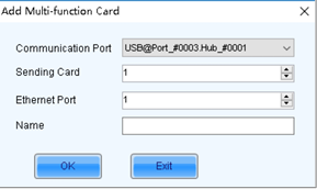
Ethernet port connection
Below shows the user interface of an Ethernet port connection that is added successfully. The following procedure takes Ethernet port connection as an example to illustrate the function.
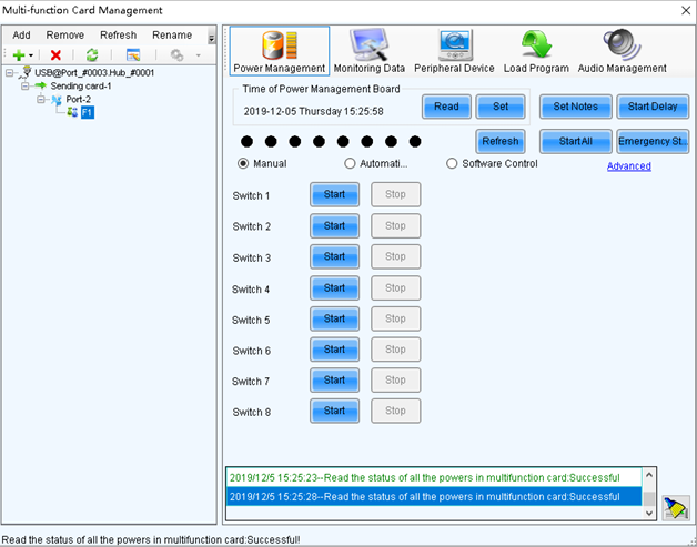
Ethernet port connection UI
- Step 4: Use any of the following functions as needed.
Power Management
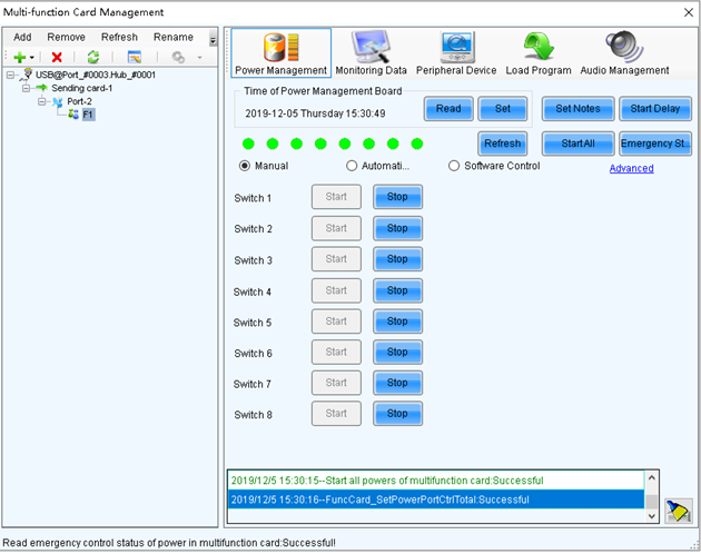
Power Management
- Read: Read the time from the multifunction card.
- Set: Set the multifunction card time to the PC time.
- Set Notes: Write notes for the power supplies.
- Start Delay: Set the delay time for powering on the multifunction card.
- Refresh: Read back the multifunction card information.
- Start All: Start all power supplies.
- Emergency Stop: Stop all power supplies. When the emergency stop operation is executed, automatic control is invalid.
- Manual: Start or stop the power supplies manually.
- Automatic Control: Set the auto start and stop time for the power supplies.
- Software Control: Set the power control schedule. Click Edit to customize the power control list. Click View Log to view the power control log.
- Advanced: Set the time for the automatic time synchronization between the multifunction card and PC.
Monitoring Data
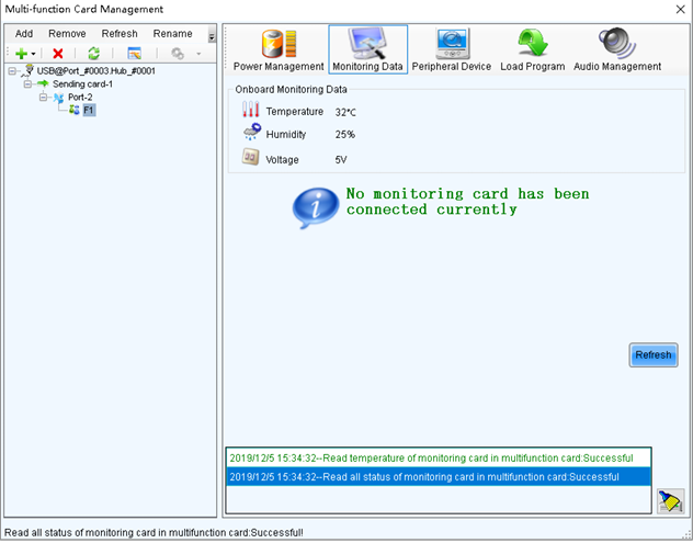
Monitoring Data
View the monitoring data of both multifunction card itself and its connected monitoring card.
Peripheral Device
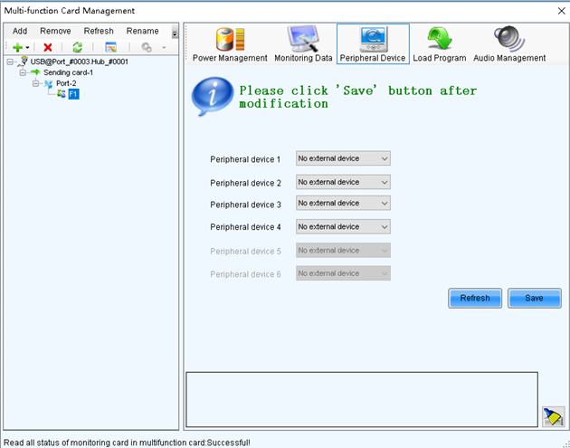
Peripheral Device
Add the peripheral devices connected to the multifunction card, including the light sensors and external 3D emitters.
Load Program
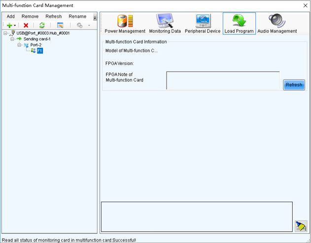
Load Program
Click Refresh to view the multifunction card model, FPGA version and FPGA note. Type "admin" to access the options for program loading.
- Select Load program for selected Multi-function Card or Load all programs for Multi-function Card.
- Click Browse to select the program package.
- Click Change to load the selected program.
- Click Exit to hide the program loading options.
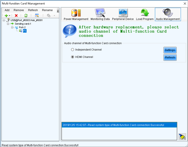
Audio Management
Audio Management
Set the audio channel connected to the multifunction card, including the independent channel and HDMI channel.
- In the Multifunction Card area, you can view the connection status of the relay, set the start delay duration, and assign group tags to the relays on the multifunction card. You can also enable or disable the relay switch as needed.
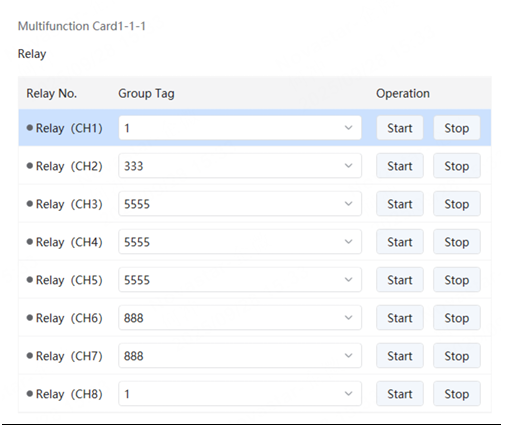
Relay status
The group tag Screen Power indicates the board power.
3.11.2. Sensor
How to install 4G module to TB series
- TB1-4G, TB2-4G (for example)
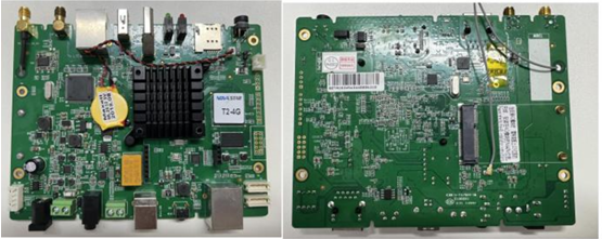
TB1-4G / TB2-4G
For TB1-4G and TB2-4G, you need to remove the case and locate the 4G module mounting slot on the back of the card body.
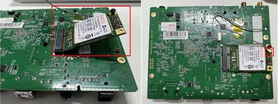
4G module slot
Insert the 4G module diagonally into the card slot and secure the module with screws; Install the IPEX port of the adapter cable on the card into the MAIN port of the 4G module; Install the 4G antenna into the 4G antenna port.
- TB30, TB40, TB50, TB60 (for example)
TB30/TB40/TB50/TB60
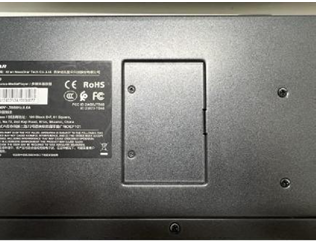
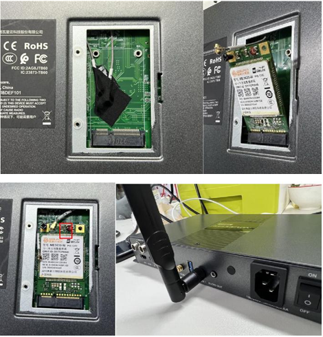
Remove the screws from the bottom of the TB box and open the back cover; Insert the 4G module diagonally into the slot and fix the module with screws; Remove the protective film and select the adapter cable labeled "4G"; Install the IPEX port of the adapter cable into the MAIN port of the 4G module; Install the 4G antenna into the COM1 port (reserved port for 4G antenna).
4G module installation
- TB10
TB10
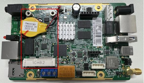
To install the TB10, remove the case and locate the 4G module mounting slot on the front of the card body.
TB10 4G slot
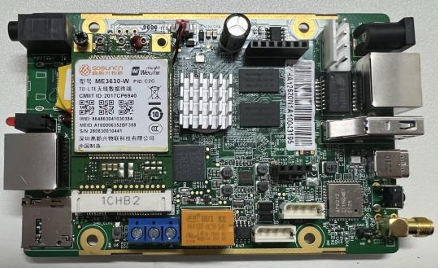
Insert the 4G module diagonally into the card slot and fix the module by screws; Install the IPEX port of the 20cm IPEX to SMA*1 adapter cable into the MAIN port of the 4G module; connect the SMA port of the other end to the COM1 port of the TB10 (4G antenna reserved port); Install the 4G antenna into the 4G antenna interface.
Install Lora Module on Taurus board (Take T6 as an example)
- Install Lora antenna to the Lora module.
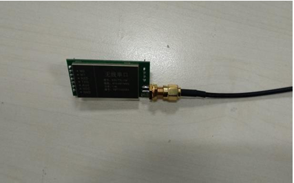
Lora antenna
- Vertically insert the Lora module into the board.
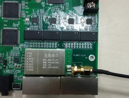
Lora module
⚠️ Note:
- T3 has the same installation method with T6.
- If the Taurus board is installed inside the cabinet, the Lora module needs to be put outside of the cabinet in case of signal interference, worsening the sync effects. Please buy extended antennas if the original antenna is too short.
- If relay board has been installed, then the Lora module needs to be inserted on the relay board.
Install Lora Module on a TB series box
- Remove the screw on the top, left, and right side to pull it apart.
- Remove the cap of the COM2 port on the back panel.
- Connect the antenna adaptor cable with the Lora module.
- Vertically insert the Lora module with the antenna adaptor cable into the board.
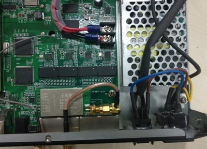
Lora module on TB box
⚠️ Note:
- TB3, TB4 and TB8 have the same installation method with TB6.
- The adaptor cable is an optional accessory, so please buy it additionally.
- If the Taurus box is installed inside the cabinet, the Lora module needs to be put outside of the cabinet in case of signal interference, worsening the sync effects. Please buy extended antennas if the original antenna is too short.
If the hardware connection includes a sensor, it is necessary to logically connect the sensor in ViPlex Express, so that the player can collect environment monitoring data through the sensor. When the interface displays the RF Synchronization information, it indicates that the current player has enabled environment monitoring data synchronization. For related operations, see RF Time Synchronization. RF Synchronization divides into master device and slave device. Users only need to configure the sensor on the master device, while the slave device remains synchronized with the environment monitoring data of the master device via RF signals.
3.12. Export Logs
- Step 1: Choose Settings > Advanced Login from the menu bar at the upper left of the interface.
- Step 2: Enter selftest/666888/novasoft in the window that appears and click OK.
- Step 3: Choose Debugging > Debugging Tool from the menu bar at the upper left of the interface.
- Step 4: Under the Logs tab, you can configure Device System Log, Device Operation Log, Control Computer Log.
Device System Log: Users can download, configure and clear logs as needed.
- Download: After selecting a save path, click Download to download the system log. Once the download is complete, click Please check it to view the system log.
Download system log
- Configure: Click Configure, select the log type, level, total package size, and each record size in the System Log Configuration window that appears, then click OK.
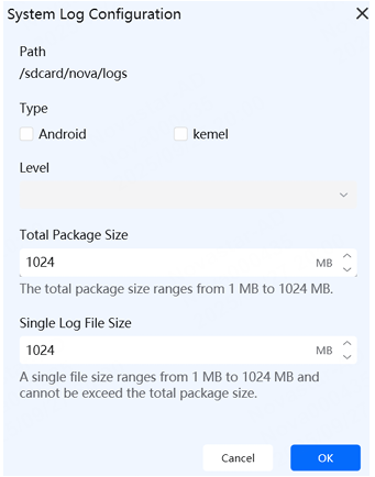
System log configuration
- Clear: Click to clear the system log.
Device Operation Log: After selecting a save path, click Download. Once the download is complete, you can view the device operation log.
Control Computer Log: After selecting a save path, click Download. Once the download is complete, you can view the control computer log.
3.13. Ultra-wide Screen Configuration
3.13.1. Required Software and Hardware Devices
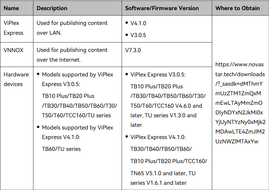
Required devices
3.13.2. Ultra-Long-Screen Content Playback Instructions
New Method
Screen Configuration
Prerequisites: ViPlex Express V4.1.0 supports ultra-long screen configuration for TB30/TB40/TB50/TB60/TB10 Plus/TB20 Plus/TCC160/TN65, and the entire TU series.
Operating Procedure
- Step 1: Select the target screen under My Screens.
- Step 2: Choose Monitor & Control > Screen Topology.
- Step 3: Enter selftest/666888/novasoft and click OK.
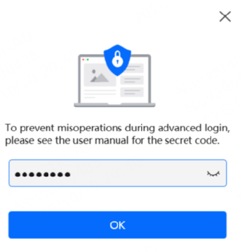
Screen topology login
- Step 4: In the Number of Receiving Cards area on the right side of the interface, set the Number of Columns and Number of Rows for the receiving cards.
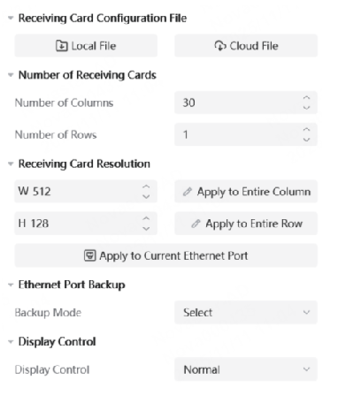
Receiving card settings
- Step 5: Select an output port at the bottom of the interface. Once the port is selected, the capacity of the first receiving card will be automatically read.
- Step 6: (Optional) In the Receiving Card Resolution area, set the load capacity for the receiving card.
- Apply to Entire Row: Apply the pixel height loaded by the currently selected receiving card to all receiving cards in the same row.
- Apply to Entire Column: Apply the pixel width loaded by the currently selected receiving card to all receiving cards in the same column.
- Apply to Current Ethernet Port: Apply the current pixel width and height to all the receiving cards connected to the output port.
- Step 7: Set the topology for the receiving cards. Click or drag the mouse to connect the receiving cards. During connection, the load capacity defaults to the current value, but you can modify the load capacity of the receiving card if needed.
- Step 8: Repeat Step 5 to Step 6 to set the connection of the receiving cards loaded by the other output ports.
- Step 9: Click Apply at the bottom right of the interface to send the configuration information to the hardware.
Playlist Creation
Operation Procedure
- Step 1: From the homepage of ViPlex Express, select Playlist to enter the playlist interface.

Playlist interface
- Step 2: Next to the Playlists tab, click to create a playlist.
- Step 3: After a playlist is created, view the playlist information (resolution, size, creation time, and update time).
- Step 4: At the bottom of the playlist editing page, click Import Media, then select the type of media from the local file explorer, and click Open.

Import media
- Step 5: Hover the mouse over the media, click or drag the media into the media editing area.
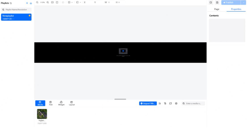
Media editing area
- Step 6: Once the media is added to the media editing area, configure the media properties under the Properties tab on the right side of the interface.
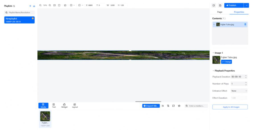
Media properties
- Step 7: After the editing is done, click Save.

Save playlist
- Step 8: (Optional) Click at the top right of the page to preview the current page.
- Step 9: After the editing is done, click Publish and select the screen to publish the playlist.

Publish playlist
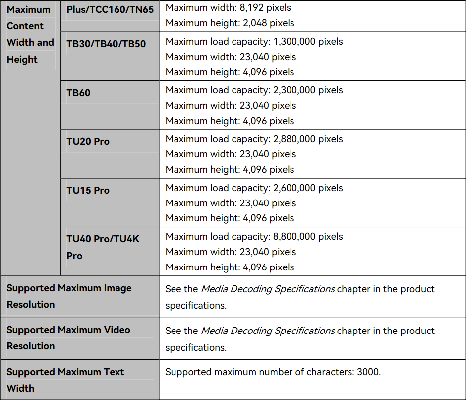
Publish confirmation
⚠️ Note:
- To ensure smooth playback, it is not recommended to simultaneously play videos and text.
- For media codec specifications requirements, see the product specifications.
Old Method
Application Example
Example: The screen resolution is 23040 × 64. The TB60 multimedia player works with the screen to play content. The configured screen width in the following receiving card connection diagrams is 3840 pixels (512×7+256) and the configured screen height is 384 pixels (64×6, less than 512).
- Number of parts: 23040/4096=5.625, rounded to 6
- Screen width to be configured: 23040/6=3840
- Screen height to be configured: 64×6=384
Screen Configuration
- When users set the connection between receiving cards, it is necessary to calculate the number of parts to cut due to the limitation of the maximum pixel width supported by the device and the connection must be a Z-shaped pattern as shown in the picture.
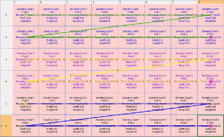
Z-shaped pattern
- To set receiving cards to blank, you can choose the receiving cards only at both ends, as shown in picture.
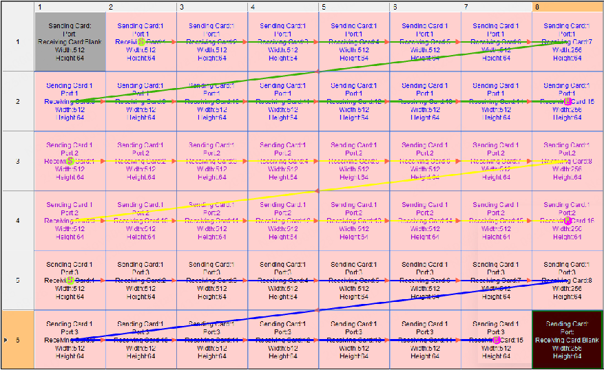
Blank receiving cards
Content Creation (ViPlex Express V3.0.5)
Operating Procedure
- Step 1: On the home page of ViPlex Express, choose Solutions to access the solution management page.
- Step 2: Click New and select Ultra-Long Screen from the drop-down menu.
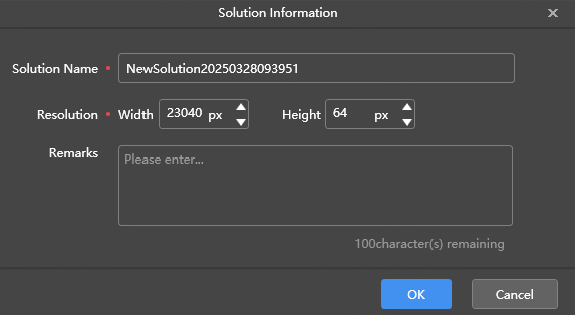
New ultra-long screen
- Step 3: Set a solution name and resolution, and click OK. Edit the solution according to the actual screen size. (The following takes the creation of a video solution for ultra-long screens as an example.) The page media editing area is displayed in proportion to the actual screen size.
⚠️ Note: If the receiving card at the starting position is set to blank during screen configuration, the pixel width of the blank must be added to the pixel width of the solution resolution.
- Step 4: At the top of the editing page, click Video.
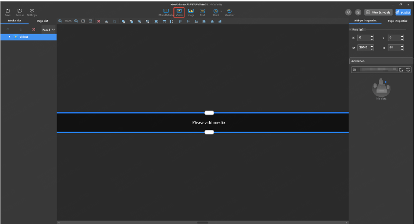
Video solution

Video editing
- Step 5: On the Widget Properties tab on the right of the solution editing page, click and select media files from the local folder (multiple videos can be selected for playlist playback).
⚠️ Note: If the receiving card at the starting position is set to blank during screen configuration, the pixel width of the blank must be added to the horizontal position of the added media.
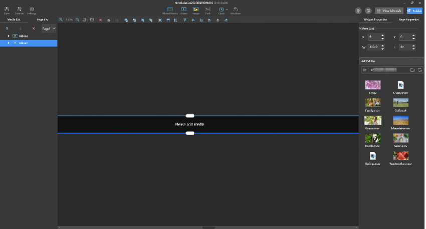
Media position

Media horizontal position
- Step 6: (Optional) At the top right of the page, click to preview the current page.
- Step 7: After the solution editing is done, click Publish and select players to publish the solution.
Ultra-Long-Screen Content Playback Parameters
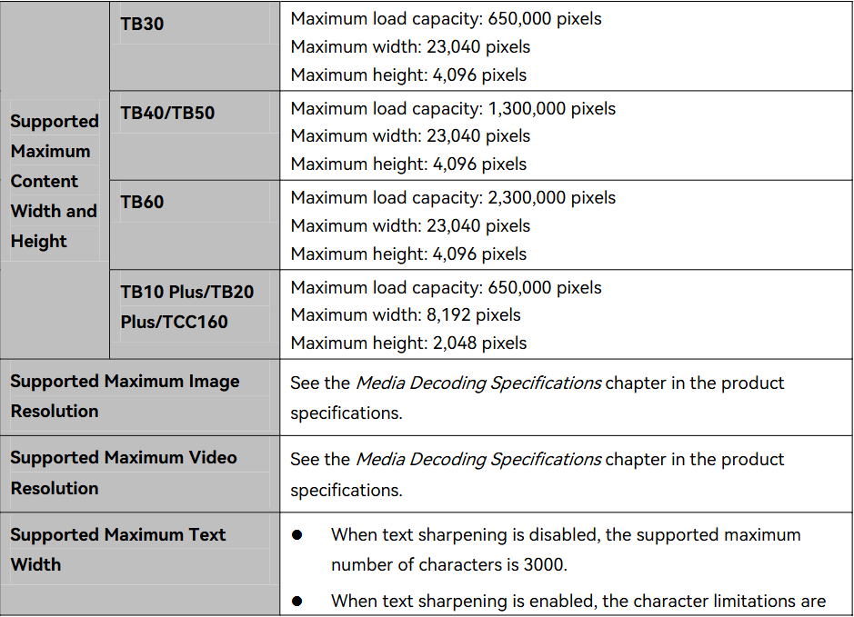
Playback parameters
⚠️ Note:
- To ensure smooth playback, it is not recommended to simultaneously play videos and text.
- For media codec specifications requirements, see the product specifications.
Ultra-wide screen limits and TU-series folded loading
- Text playback: When the screen width exceeds 16384 pixels, text playback is not supported — only images and videos.
- Image limits: Up to 10 images at most 1080p simultaneously; up to 2 images when larger than 2K and up to 4K.
- Synchronous playback is not supported on ultra-long screens.
- TU series (multifunction card) folded loading: TU20 / TU20 Pro support up to 6 folds with a point-to-point loading limit of 2.88M pixels; TU15 series up to 6 folds with 2.25M pixels; TU4K point-to-point output up to 8.84M pixels. After fixing the connection diagram, the device automatically enables scaling — disable scaling manually to keep point-to-point display (on TU1.4, disable "scaling enabled" in LCT).