H Series
Configuration
Screen Setup
1. H Configuration Preparations
1.1. Hardware Connection
Input Cards
The H series supports a variety of input sources. Connect the input sources to the matched input card connectors.
- DVI, HDMI, SDI, CVBS, VGA or DP input sources: Connect the input sources to the matched input card connectors using corresponding cables or converter cables.
- IP camera sources: Connect the input source to the Ethernet port of the H_2xRJ45 IP input card using an Ethernet cable.
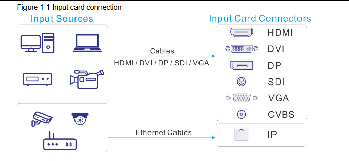
Input cards
Available Input Cards
The H series uses a modular card-based architecture. The number of input cards and input routes depends on the model: H2 (2U, up to 4 cards / 16 routes), H5 (5U, up to 10 cards / 40 routes), H9 (9U, up to 15 cards / 60 routes), H15 (15U, up to 30 cards / 120 routes), H20 (20U, up to 40 cards / 160 routes). Input cards are hot-swappable.
| Input Card | Connectors | Max Resolution |
|---|---|---|
| H_1xHDMI2.1+1xDP1.4 input card | HDMI 2.1 / DP 1.4 (either-or) | 8K@30Hz |
| H_2xHDMI2.0+2xDP1.2 input card | HDMI 2.0 + DP 1.2 | 4K@60Hz |
| H_1xHDMI2.0+1xDP1.2 input card | HDMI 2.0 / DP 1.2 (either-or) | 4K@60Hz |
| H_2xHDMI2.0 input card | HDMI 2.0 | 4K@60Hz |
| H_1xHDMI2.0 input card | HDMI 2.0 | 4K@60Hz |
| H_4xHDMI input card | HDMI 1.3/1.4 | 2K@60Hz (SL) / 4K@60Hz (DL) |
| H_2xDP1.2 input card | DP 1.2 | 4K@60Hz |
| H_1xDP1.2 input card | DP 1.2 | 4K@60Hz |
| H_2xDP1.1 input card | DP 1.1 | 4K@30Hz |
| H_4xDVI input card | DVI (SL/DL switchable) | 2K@60Hz (SL) / 4K@60Hz (DL) |
| H_1x12G-SDI input card | 12G-SDI (compatible with 3G/HD/SD-SDI) | 4K@60Hz |
| H_4x3G-SDI input card | 3G-SDI (compatible with HD/SD-SDI) | 1080p@60Hz |
| H_1xST2110 input card | 25G optical (SMPTE ST 2110, primary/backup redundancy) | 4K@60Hz |
| H_2xRJ45 IP decoding card | 2x RJ45 Gigabit Ethernet | Up to 4x 800W or 64x D1 per card; RTSP/GB28181/ONVIF, H.264/H.265 |
| H_1xNDI input card | RJ45 Gigabit Ethernet | Up to 4K (NDI decoding) |
| H_4xoptical input card | 4x 10G optical (single-mode/multi-mode optional) | 4K@30Hz |
| H_4xVGA input card | VGA | 1920x1200@60Hz |
| H_2xCVBS+2xVGA input card | CVBS + VGA | VGA: 1920x1200@60Hz; CVBS: PAL/NTSC |
| H_4xHDBaseT input card | HDBaseT (RJ45) | Long-distance transmission |
| H_2xAudio input+2xAudio output card | Phoenix terminal audio | 2x audio input + 2x audio output |
| H_standard control sub-card | RS232/485, Ethernet, I/O, relay, IR | For third-party control systems |
⚠️ Note: Some input cards (e.g. H_2xDP1.2 and H_1xNDI input cards) are only compatible with specific models. Refer to the corresponding model's datasheet when selecting cards. A single card slot supports capacity switching, e.g. 4x 2Kx1K@60Hz, 2x 4Kx2K@60Hz or 1x 8Kx4K@30Hz.
Output Card
The H series provides two kinds of LED 4K sending cards: H_16xRJ45+2xfiber sending card and H_20xRJ45 sending card.
- When the H_16xRJ45+2xfiber sending card is used for output, the OPT ports copy the outputs on the Ethernet ports. OPT 1 copies and outputs the data on Ethernet ports 1–8. OPT 2 copies and outputs the data on Ethernet ports 9–16.
- Via Ethernet port: Connect the Ethernet ports directly to the LED screen based on the screen structure.
- Via OPT port: OPT ports are used for long-distance transmission. Connect the OPT ports to a fiber converter firstly, and then connect the fiber converter to the LED screen.
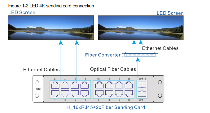
Output card
⚠️ Note: The H_20xRJ45 sending card is connected and configured in the same way as the H_16xRJ45+2xfiber sending card.
- When the video output card is used for output, the LED screen can be loaded by the sending device and the LCD screen can be loaded directly.
- Via Ethernet cable: To load the LED screen, connect the output card connectors to the input connectors of the sending device, and connect the sending device to the LED screen via Ethernet cables, as well as configure the screen on the sending device.
- Via video cable: To load the LCD screen, connect the output card connectors to input connectors of the LCD splicing screen via video cables.
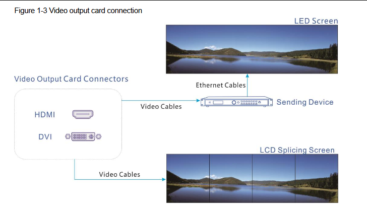
Video output card
Power Supply
Connect the power connector on the rear panel to the electrical outlet using the supplied power cord.
Control Card
You can control the H series devices on a control PC through either of the following two methods.
- Method I: Direct control for single-user control — connect the device Ethernet port to the control PC.
- Method II: Using a router or switch, for multiple user collaboration in a wired or wireless way — connect the Ethernet ports of both the device and control PC to the router or switch.
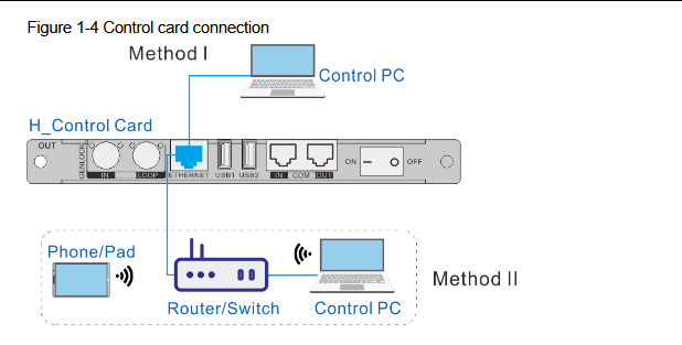
Control card
Preview Card
The H series allows you to monitor the inputs and outputs on a PC or monitor.
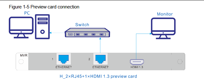
Preview card
- Via Ethernet port: Connect one of the Ethernet ports on the preview card and the Ethernet port of the control card to the same switch for the input source and screen monitoring on the Web page.
- Via HDMI connector: Connect the HDMI connector of the preview card to a monitor for on-site monitoring.
1.2. Device Login
Power On/Off
The power switch is on the H_Control card.
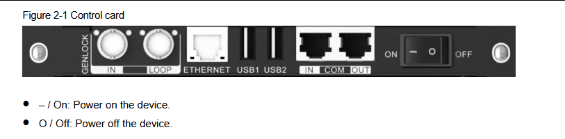
Power switch
Power On
Connect the power cord, and then set the rocker switch to ON. The home screen is displayed as follows after successfully powered on. The device IP address is displayed at the top right on the home screen. The default IP address is 192.168.0.10.
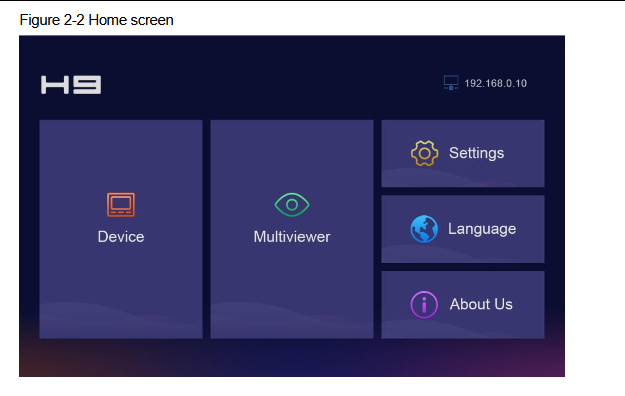
Power on home screen
Power Off
Set the rocker switch to OFF, and then disconnect the power cord if necessary.
Webpage Login
- Step 1: Make sure the H-series device is connected to your control computer via a direct Ethernet cable or through a switch.
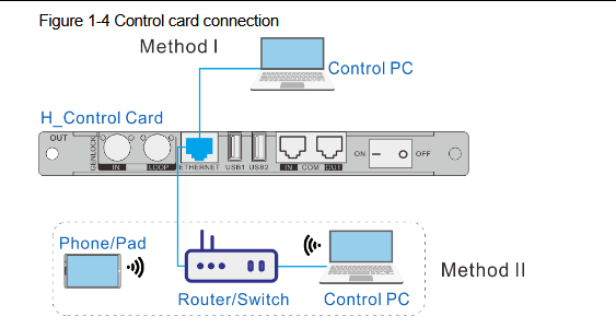
Device connection
- Step 2: Modify the IP addresses of both the computer and the device to ensure they are on the same subnet.
- When an H series device is connected directly to a control PC, the device and control PC must be on the same network segment and their IP addresses cannot conflict. For example, if the device IP address is 192.168.0.10, the IP address of the control PC must be 192.168.0.X and X cannot be 10.
- When an H series device is connected to a control PC using a router or switch, you must set to automatically get the IP address, and select Obtain an IP address automatically for the network settings on the control PC.
- a. Go to Settings > Communication from the home screen to enter the network settings screen.
- b. Click the IP Settings tab to enter the IP settings screen.
- c. Set the mode to Automatic.
- d. Click Main at the top left to return to the home screen and the current device IP address appears at the top right.
- e. Select Obtain an IP address automatically on the Internet protocol properties window on the control PC. The router or switch will assign the IP addresses to the device and control PC automatically.
- Step 3: Open the suggested web browser on your computer, enter the device IP address in the address bar, and then press Enter to jump to the login interface for the Web page for the H series devices.
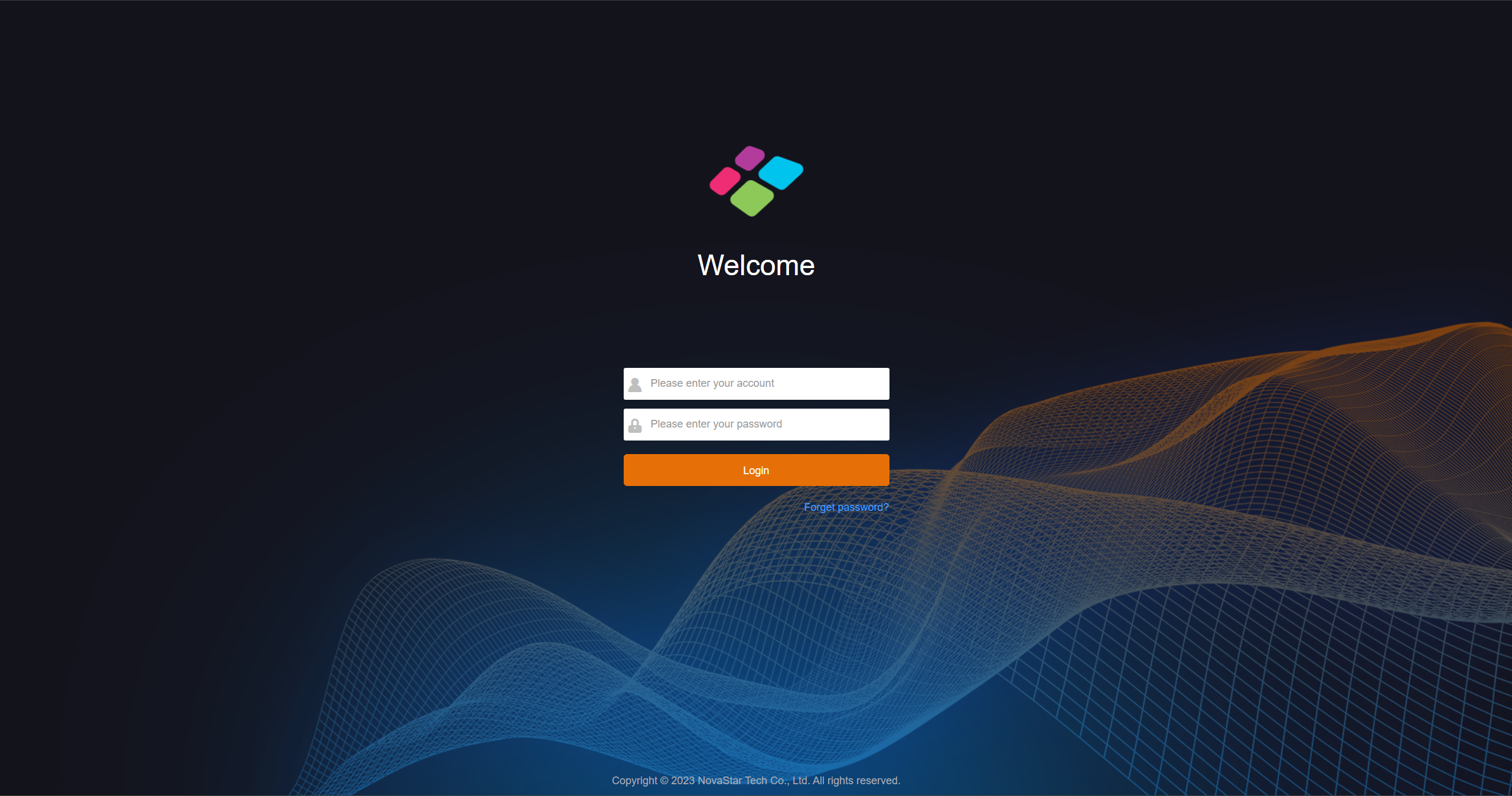
Login interface
- Step 4: Enter the user name and password, and click Login to log in to the Web page. The default user name and password are both "admin".
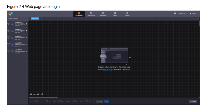
Login page
1.3. Firmware Upgrade
The H series supports firmware update through the Web page. Make sure you have downloaded the update package from NovaStar's official website before the update. The system supports the update for the control card, AUX and MVR cards, input cards and output cards. You can select to update a single component or the whole unit.
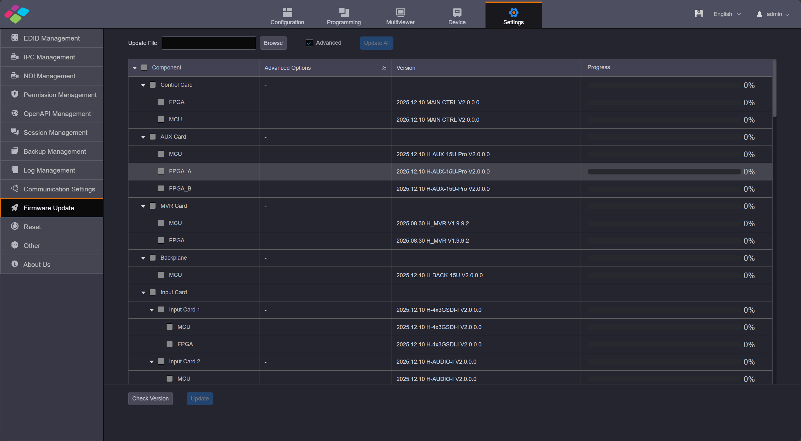
Firmware update
The update procedure is as follows
- Step 1: Firstly, make sure you have downloaded the software package of the component to be updated from NovaStar's official website.
- Step 2: Click Settings, then click Firmware Update on the left to enter the update page.
- Step 3: Click Browse to load the update package with .zip format.
- Step 4: Click Update All to update all components automatically, the device will restart when it finishes. When you select Advance Update, you can choose to upgrade a specific sub-card individually.
⚠️ Note:
- To ensure a smooth update progress and complete data compatibility, please follow the specified intermediate version sequence for step-by-step update when updating from V1.0.0.0 to V2.0.0.0. Any intermediate version should not be skipped. The mandatory update sequence is as follows:
Upgrade Notes and Troubleshooting
- Do not extract the update package: Select the .zip package directly. Extracting it before upgrading can cause failures.
- Avoid downgrading: Released versions are stable. If an upgrade fails, first retry the same version instead of downgrading.
- If the Web page reports
fileoversize: The update package is too large. Upgrade the control card first — copy the package, keep only theH_Ctrlfolder, recompress it to .zip, upgrade the control card, and then perform a full-unit upgrade. - Restore factory settings after upgrading: The latest version does not delete user data by default. It is recommended to restore factory settings after the upgrade to avoid data compatibility issues.
- Double-check the version after upgrading: Besides the version shown on the Web upgrade page, also check the detailed MCU and FPGA versions on the device page. If the version appears unchanged after a normal upgrade, open the
.xmlfile inside the sub-card program with Notepad — if the version matches the upgrade page, the upgrade is normal. - H2 intermittent upgrade failure (H2 only): When the aux hardware version next to the control card is 2.0, clicking update on the Web page may trigger sub-card MCU/FPGA upgrade failure and aux exceptions. Refer to the dedicated upgrade package
V2.0.0.CTM.1200.zipand its instructions. - Sub-card FPGA not actually updated: If the Web page shows the latest version but the device page still shows an old FPGA version, the sub-card was previously upgraded unsuccessfully. Verify the MCU/FPGA versions on the device page after upgrading.
- General failure flow: 1) Retry the same version. 2) If it still fails, check whether the control card program is too old — upgrade the control card first, then the whole unit. 3) If a sub-card upgrade fails, refer to the H/E series sub-card flashing method for a standalone flash. 4) Otherwise contact NovaStar technical support.
1.4. H web-Input&Output Configuration
Click the Settings on the top, the first option is EDID Management.
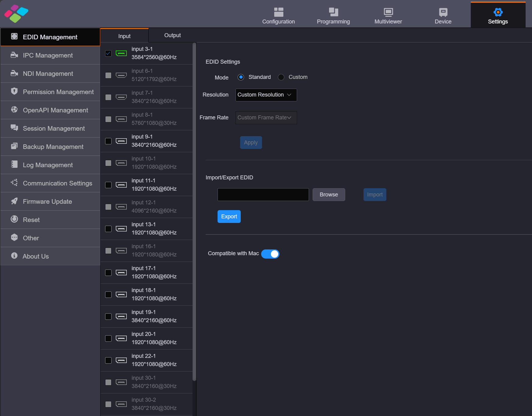
EDID Management
Input Settings
You can set the input EDID through the following three ways.
- Standard Mode: Select an input resolution from the drop-down list of Standard Resolution and frame rate, and Apply.
- Custom Mode: Set the width, height and frame rate for the input connectors and Apply.
- Import/Export EDID: Click Browse select the desired EDID configuration file, and import it for quick configuration. Click Export allows you to export the EDID file of the current interface.
- Compatible with Mac: To improve the access experience of Apple devices and enhance the native compatibility of input cards with Apple devices, the HDBASET, HDMI, and DP connectors now support the intelligent EDID management. This directly addresses the mismatch between the output resolution of Apple devices and the EDID requirements of the video wall splicer. Once enabled, Mac devices can push EDID resolutions that meet the input connectors requirements to the video wall splicer, fundamentally resolving display compatibility issues between Apple devices and the video wall splicer.
Output Settings
Video Output Card EDID Settings.
- The EDID settings section should be consistent with the EDID settings in the input section.
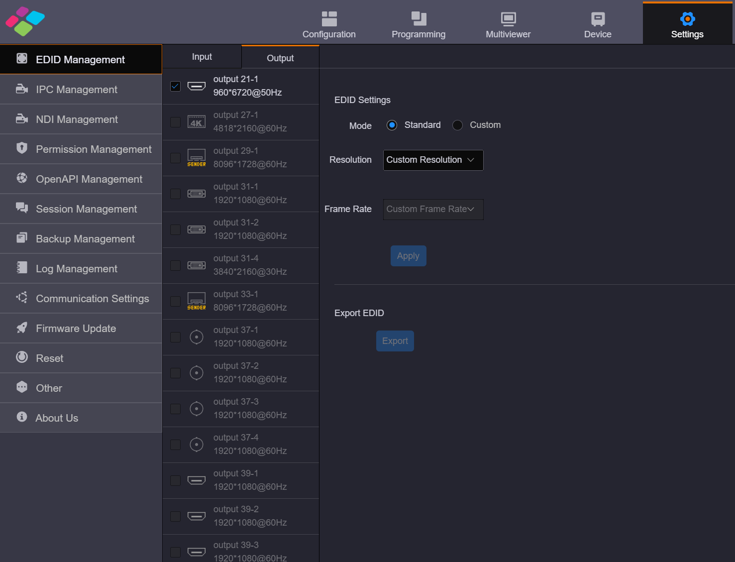
Video output card EDID
Sending card resolution settings.
- Generally, when configuring a LED screen, the output resolution of a single LED sending output card is set to the maximum width and height of the screen it loaded.
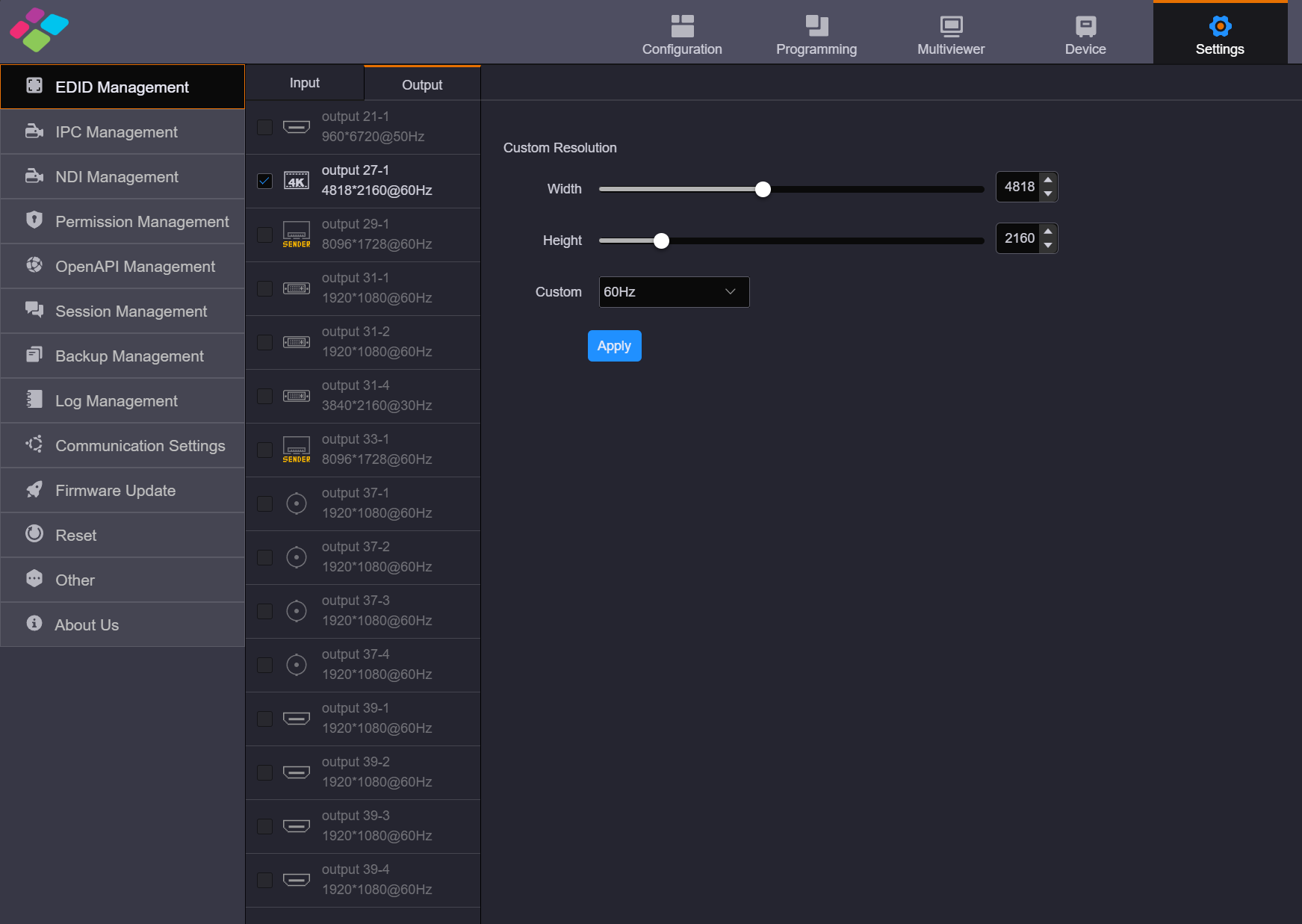
Output resolution settings
1.5. H web-Configuration&Programming
H Web Screen Configuration
After logging in, you will enter the H-Series web editing interface.
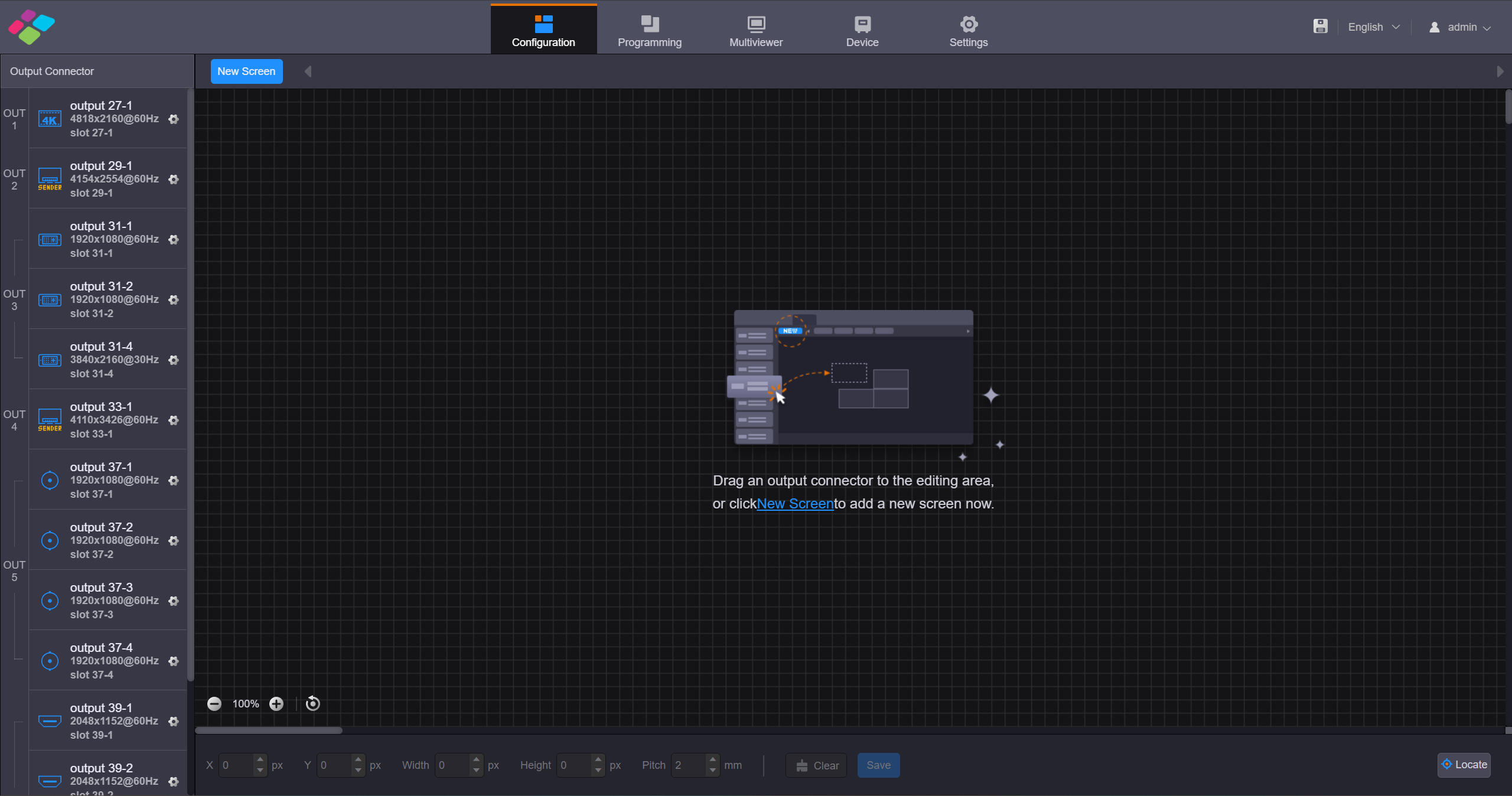
H web editing interface
Configure LED screen
- The H series as a Splicer, allows multiple output sending cards to be tiled together, enabling the loading of larger screens or the management of multiple screens. Based on the screen structure and wiring method of the current device, configure the screen and associate it with the output sending cards.
- When using the network port output sending card, the web control interface does not display the actual network output port. One network port sending card uses one 4K virtual output interface for display.
⚠️ Note:
- The H_16xRJ45+2xfiber sending card and H_20xRJ45 sending card can be configured on the same screen when they have the same frame rate.
- The fiber sending card cannot be used together with the H_20xRJ45 sending card or H_16xRJ45+2xfiber sending card to load the same screen.
- The H_4xfiber sending card (enhanced) cannot be used together with the H_4xfiber sending card to load the same screen.
H Web Operation Steps
- Step 1: Select "Screen Configuration" to enter the screen configuration interface.
- Step 2: Click "New Screen" to enter the "New Screen" editing interface.
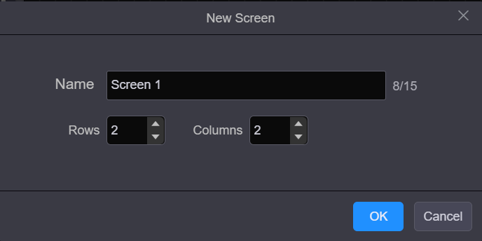
Create screen
- Step 3: Configure the number of rows and columns for the output interface splicing based on the current screen structure and the relationship with the output interface.
- Step 4: Select the output card that loads the screen, drag the sending card to the editing area of the screen, and complete the screen editing.
⚠️ Note:
- When you use the H_16xRJ45+2xfiber sending card or H_20xRJ45 sending card, it is recommended you go to Settings > EDID Management > Output to set the output resolution and frame rate first.
- When you use the H_4xfiber sending card, go to the Device page to configure the connector working mode first, and then go to Settings > EDID Management > Output to set the output resolution and frame rate.
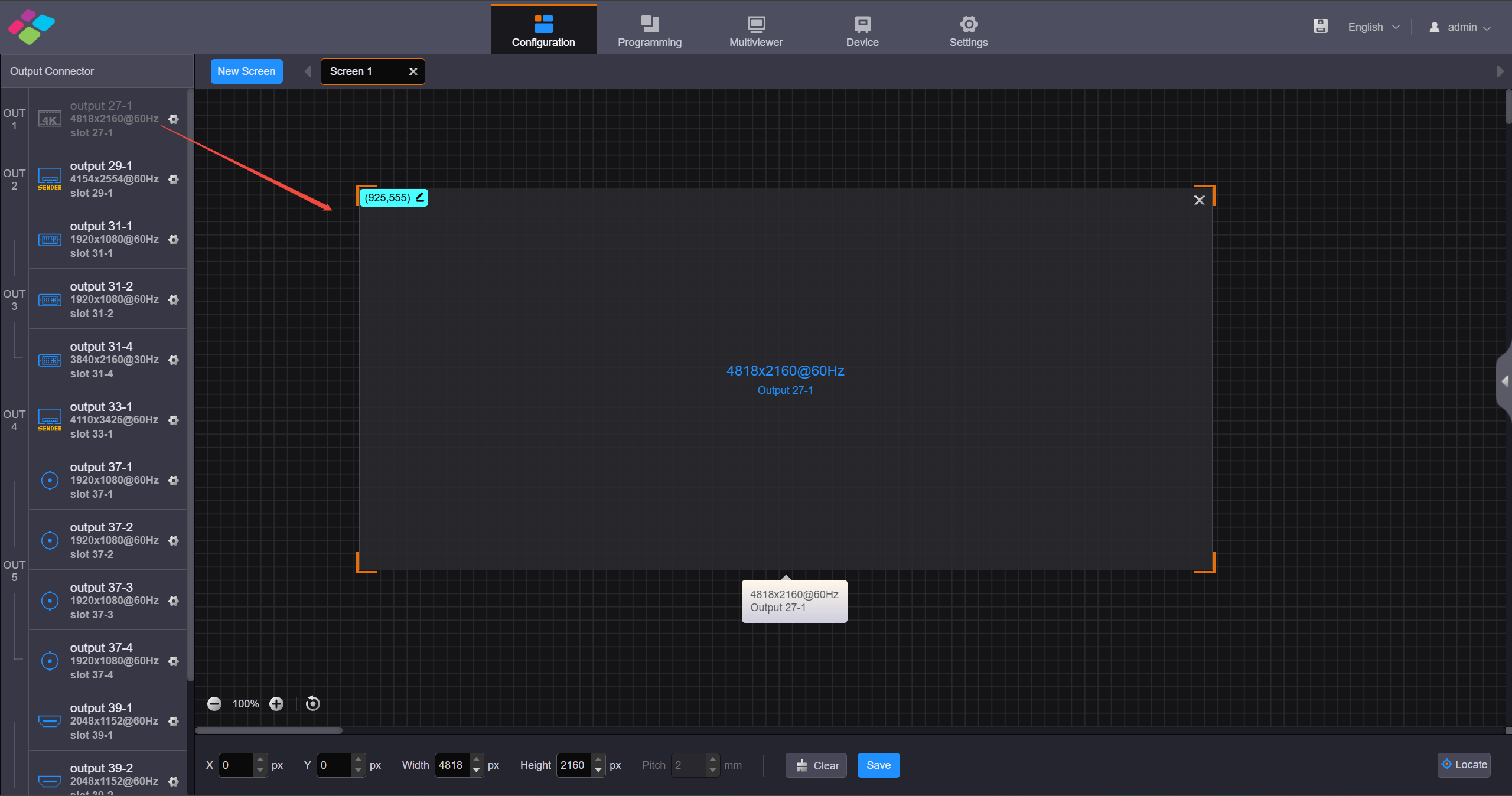
LED screen configuration
- Step 5: Click "Save" to complete screen editing.
Configure LCD screen
- Step 1: Select Configuration to enter the screen configuration page.
- Step 2: Click New Screen at the top to open the New Screen window.
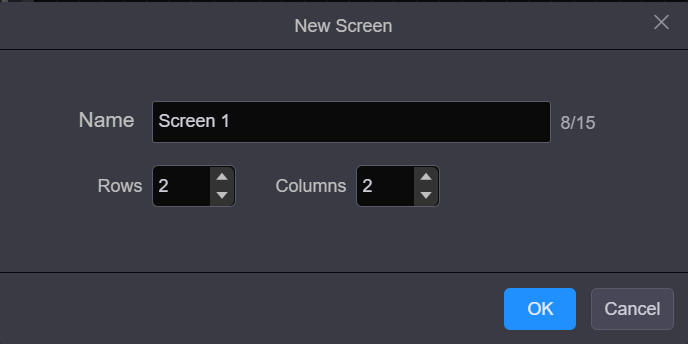
Create LCD screen
- Step 3: Select the output card that loads the LCD screen, drag the output card to the editing area of the LED screen, and complete the screen editing.
- Step 4: Click "Save" to complete screen editing.
Introduction to Programming
Once the screen configuration is complete, you can click the "Programming" interface to set the layer properties.
Add Layers
- Step 1: Click Programming to enter the layer editing page.
- Step 2: On top of the Programming page, select the screen that you will operate.
- Step 3: Click an input in the Input Signal area on the left and drag it to the editing area to add a layer.
Adjust Layers
Click the layer and you can perform the following operations.
Adjust the layer size
- Quick adjustment: Click the small square on the layer edge, and drag the square when the cursor turns to a double-sided arrow to quickly adjust the layer size.
- Precise adjustment: Enter specific numbers in the W and H text boxes below the layer editing area to precisely adjust the layer size.
Layer position adjustment
- Quick Adjustment: Place the mouse inside the layer, hold down the left mouse button and drag to quickly adjust the layer's position.
- Precise Adjustment: Enter specific numbers in the text boxes after "X" and "Y" below the layer to precisely adjust the layer's position, based on the top-left corner of the layer.
Layer Capacity Adjustment
- In the "Devices" interface, click on the input card of the input source you want to adjust, and modify the interface capacity in the "Capacity" section of the input card properties on the right.
Save Preset
- After completing the layer settings, you can save the edited content as a "preset", allowing multiple presets to cover different usage scenarios.
- Step 1: On the Programming page, click Save Preset below the layer editing area to open the preset saving window.
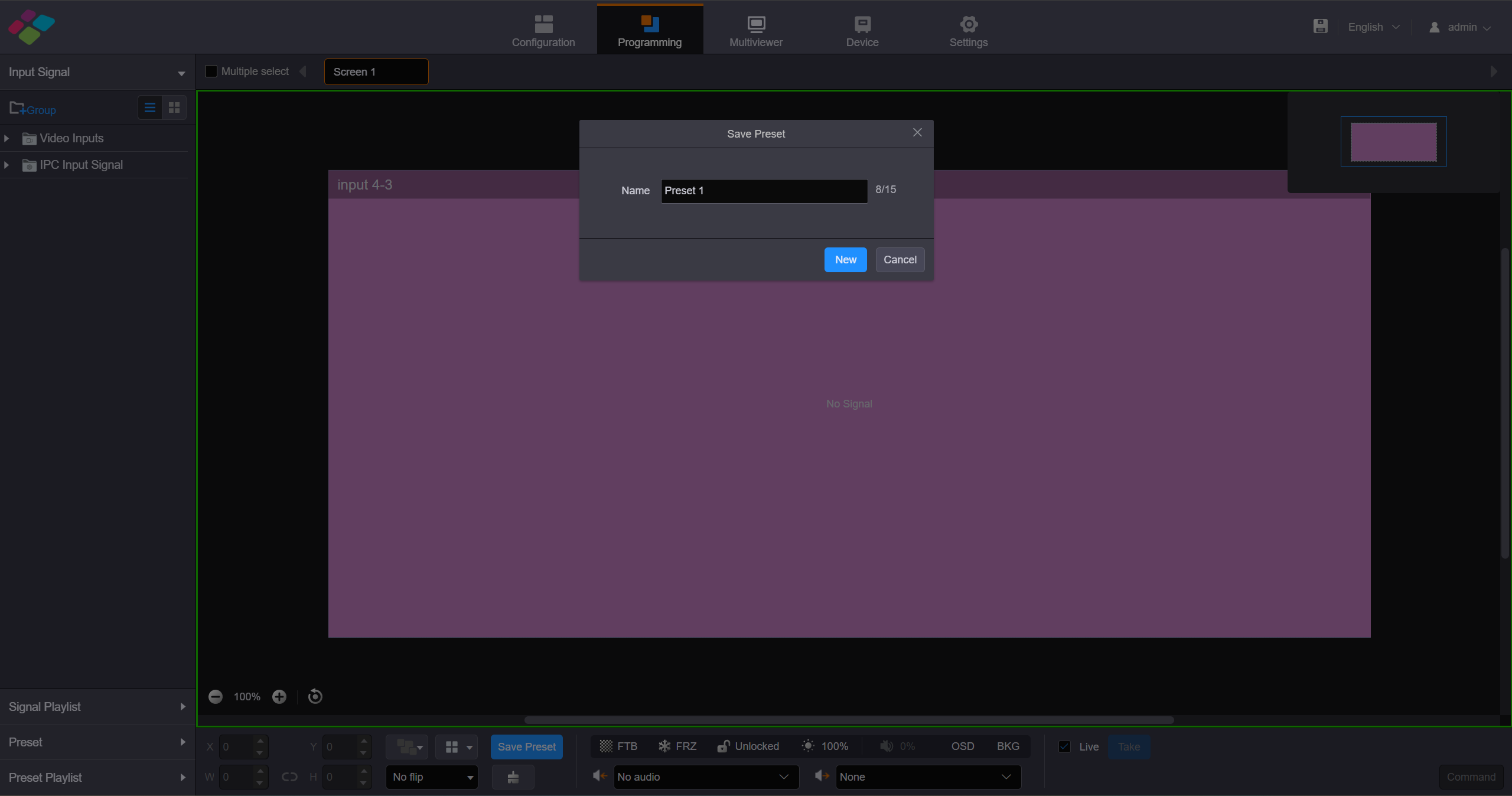
Save preset
- Fill in the scene name according to actual needs.
- Click "Save" to complete the scene saving.
- Click "Preset" on the left to open the scene list and manually switch between different scenes.
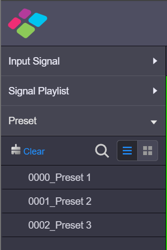
Preset switching
Add BKG
- On the Programming page, click BKG below the layer editing area to expand the BKG settings pane.
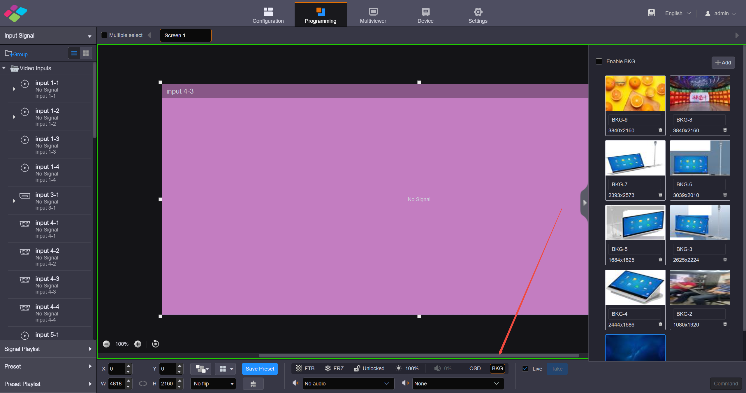
Add BKG
- Click Add to open the window where you can select and add a BKG file.
- Select the desired file and click Open to add it to the BKG list.
Add OSD
- The H series supports various OSD options, including static text OSD, dynamic text OSD, weather OSD, clock OSD and image OSD. OSD is displayed at the top level and its priority cannot be adjusted.
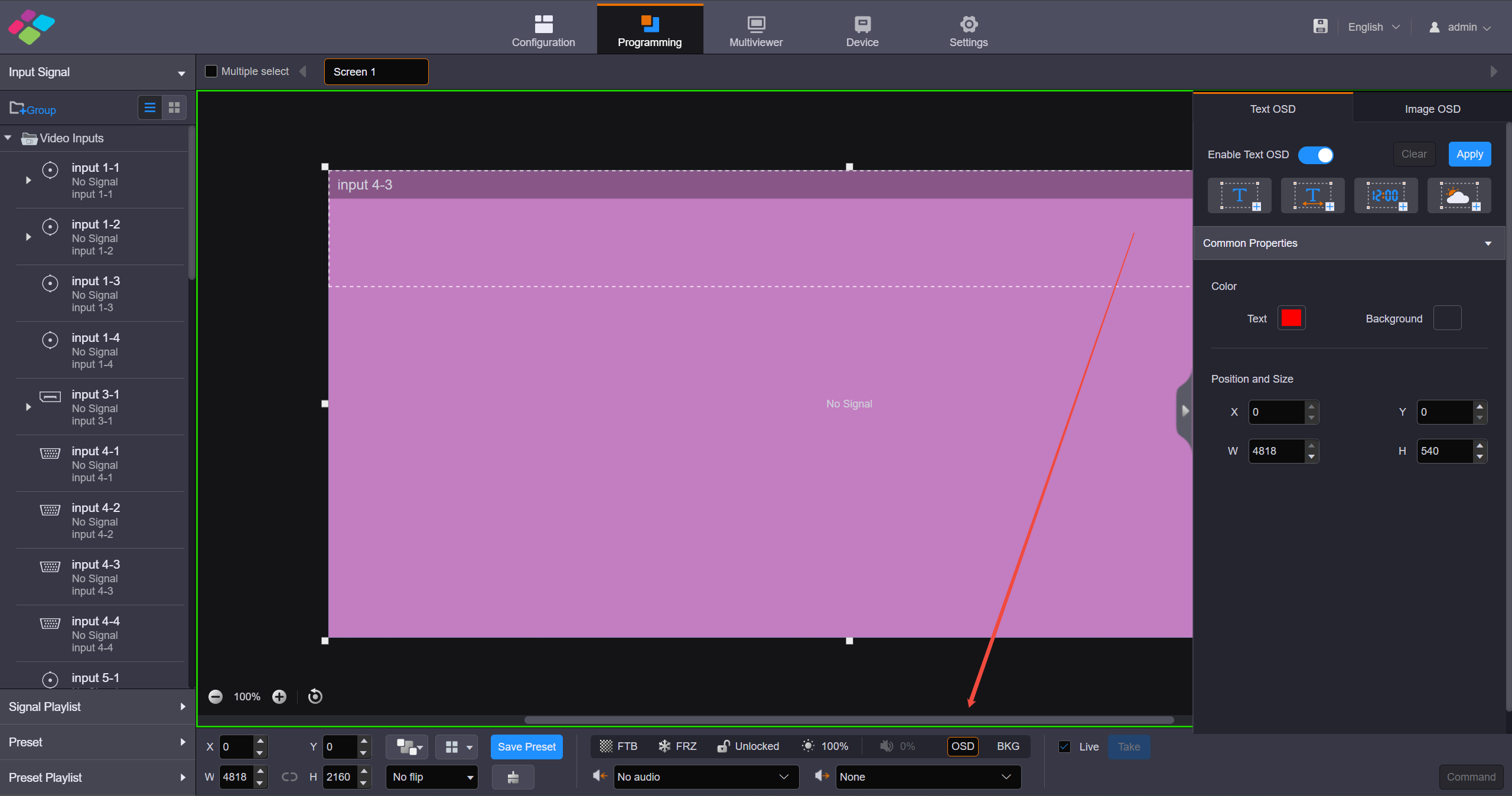
Add OSD
2. Screen Configuration
2.1. Cabinet Configuration
Configure cabinet with RCFGX file
What is RCFGX file:
An .rcfgx file is a Receiving Card Configuration file used primarily by NovaStar LED display systems. It acts as a configuration profile, containing essential parameters like resolution, scan mode, pixel mapping, and refresh rate for LED panels.
Where can you get the file:
The RCFGX file is provided as a standard working file with the cabinet upon shipment. For additional files you can contact the LED screen manufacturer's relevant staff to obtain them.
Step 1: Import .rcfgx
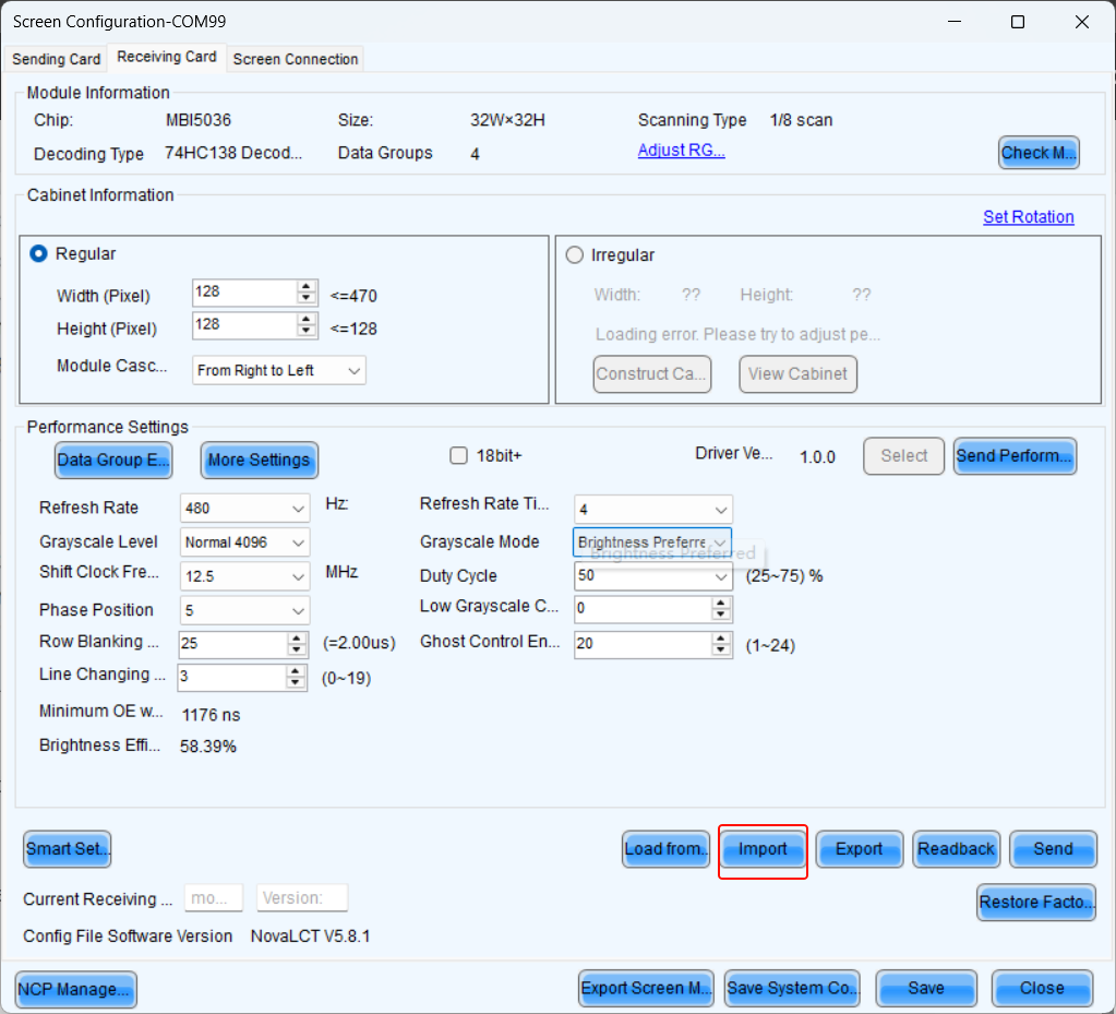
Import RCFGX
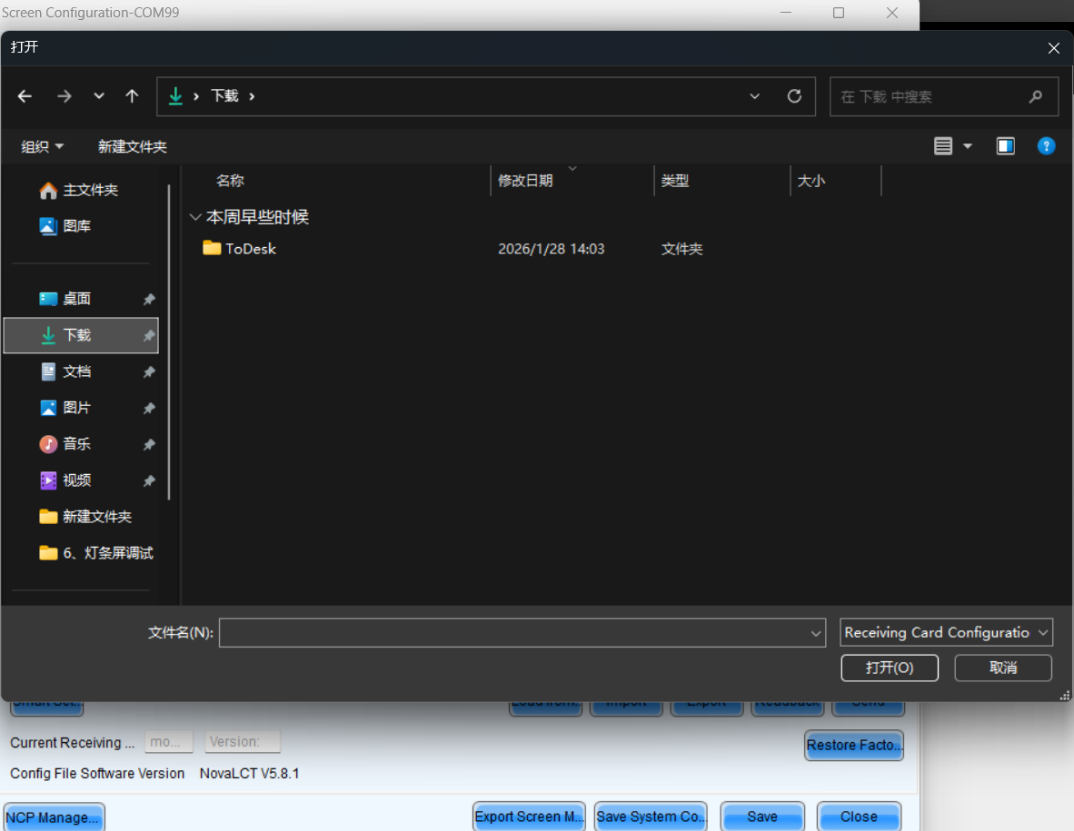
Select file
Step 2: Send .rcfgx
After importing a new RCFGX file, the parameters will not be sent directly to the receiving card. You need to click the send button. Before saving to hardware, ensure the display is functioning perfectly.
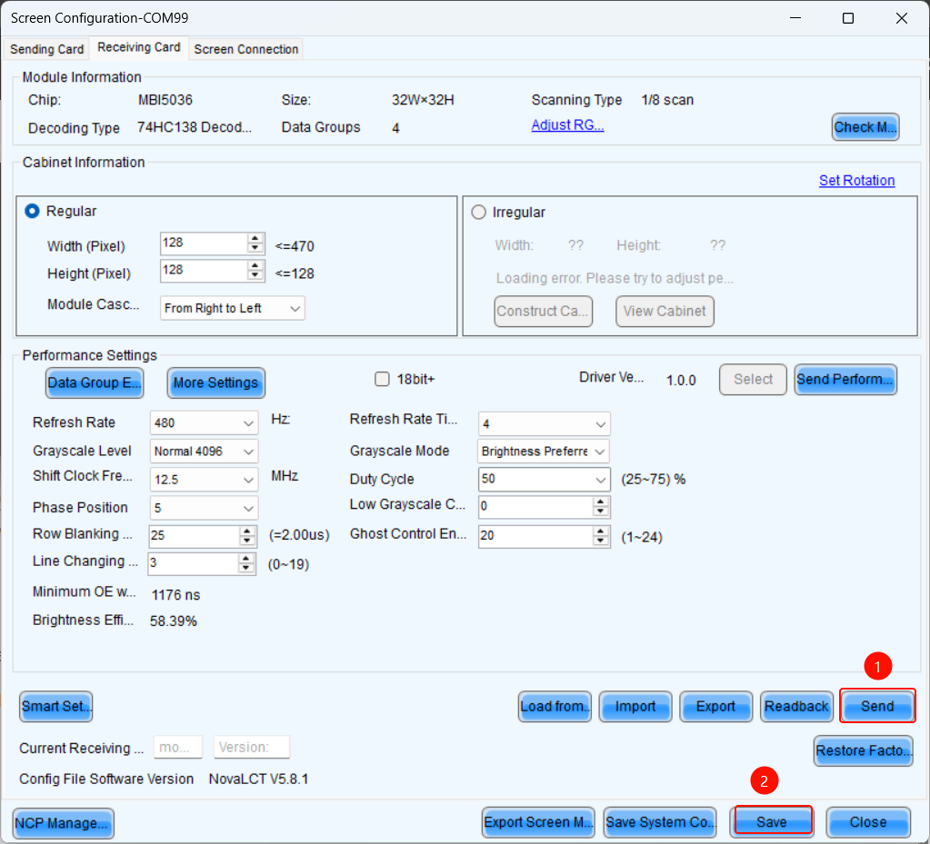
Send RCFGX
Step 3: Save .rcfgx
After successfully sending the parameters to the receiving card, click Save to store the parameters in the hardware, ensuring data remains intact after power cycling.
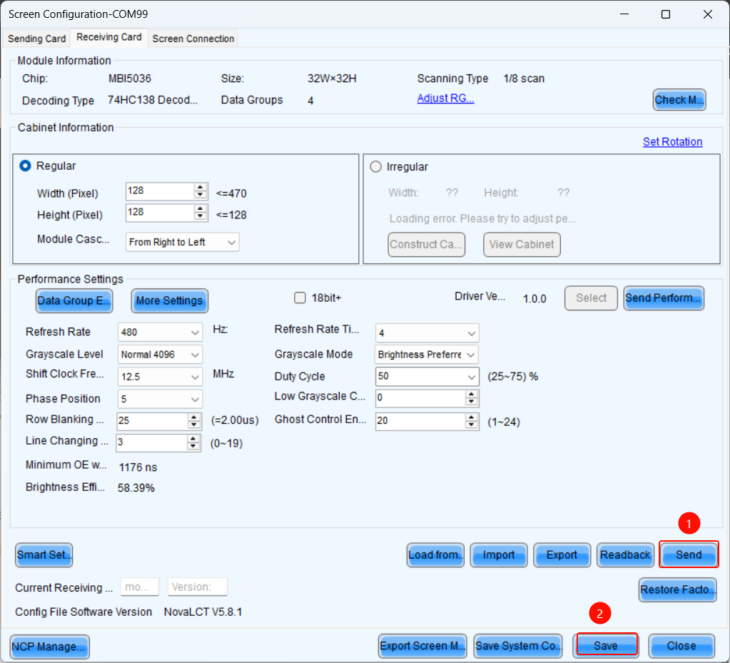
Save RCFGX
Configure cabinet with NCP file
What is NCP file:
You can click the link below to check the information about the NCP file.
- Step 1: On the Screen Configuration page, click the Receiving Card tab for NCP Management.
If the Receiving Card tab defaults to the .rcfgx/.rcfg configuration interface, click NCP Management to enter the NCP management interface.
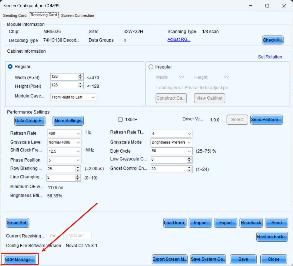
NCP Management
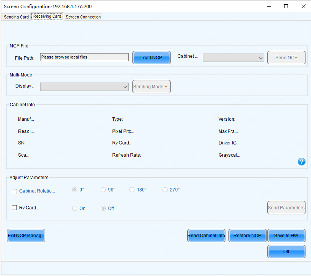
NCP Management interface
- Step 2: Click Load NCP.
- Step 3: On the pop-up window, choose an .ncp file, and click Open.
- Step 4: Send the cabinet file and display mode parameters.
- Select a cabinet file from the drop-down list and then click Send NCP.
- Select a display mode from the drop-down list and then click Send Mode Parameters.
- Step 5: On the pop-up window, select the target receiving cards and click Send.
- All Receiving Card: Send the receiving card configuration information to all the receiving cards loaded by the current sending card. If you select Reset the Starting Coordinate of Receiving Card, the starting coordinates of all the receiving cards will be reset to (0, 0). As a result, all the receiving cards display the top-left image of the input source.
- Specified Receiving Card: Send the receiving card configuration information to the specified cards by sending card, by topology, or by physical address.
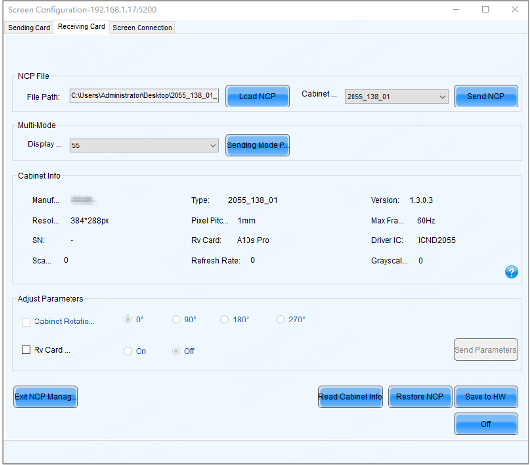
Send NCP
- Step 6: Click Save to HW.
- Step 7: Do the following as required.
Read cabinet information:
Click Read Cabinet Info, set the receiving card address on the pop-up window, and then click OK.
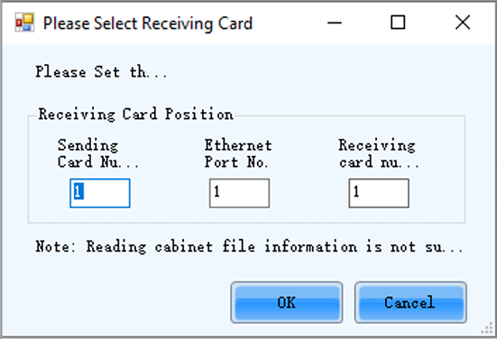
Read Cabinet Info
Restore NCP
a. Click Restore NCP. b. On the pop-up window, select the receiving cards you want to restore. c. On the Send by Topology tab, you can click Check Backup Files to check if there is a backup file in the receiving card factory area. d. Click Restore Specified Rv Cards to restore the backup file in the factory area to DDR. e. Click Save to All Rv Cards.
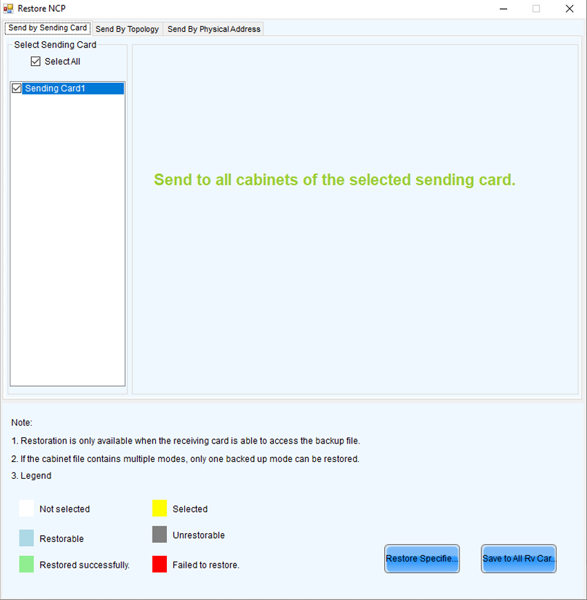
Restore NCP
Set cabinet rotation
Select Cabinet Rotation, set the rotation angle, and then click Send Parameters.
Set receiving card indicator
Select Rv Card Indicator, choose between Enable or Disable, and then click Send Parameters.
2.2. Screen Connection
NovaLCT Screen Configuration Steps
When the H_16xRJ45+2xfiber sending card, H_20xRJ45 sending card or H_4xfiber sending card is used, you must configure the screen in NovaLCT.
- Step 1: Go to User > Advanced Synchronous System User Login. Enter the password and click Login. The default password is "admin".
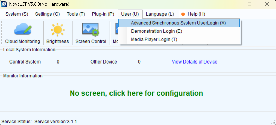
Log in to NovaLCT
- Step 2: Click on "Screen Configuration" to open the display configuration interface.
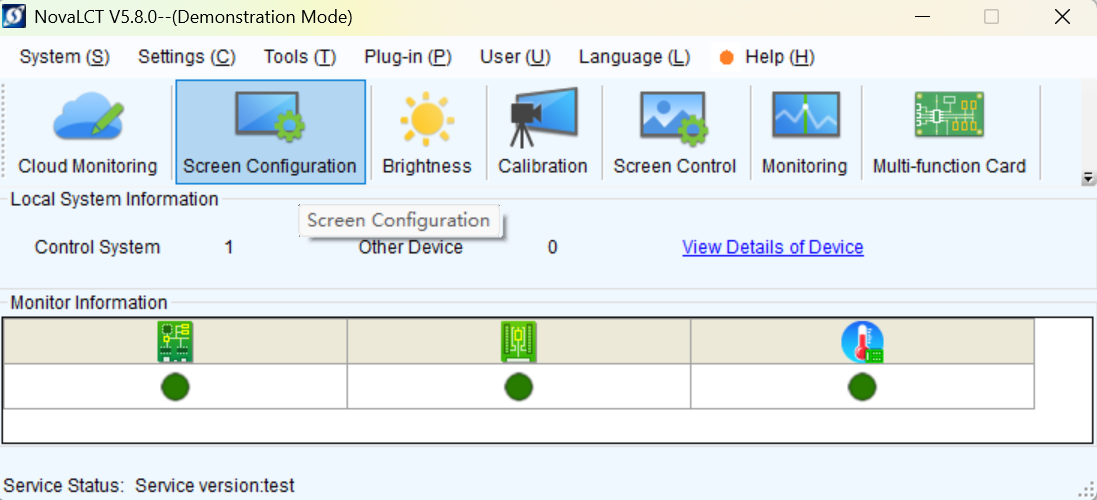
Screen configuration
- Step 3: Select a communication port and click Next.
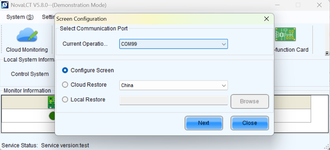
Select communication port
- Step 4: Select the Screen Connection tab to show the screen configuration settings.
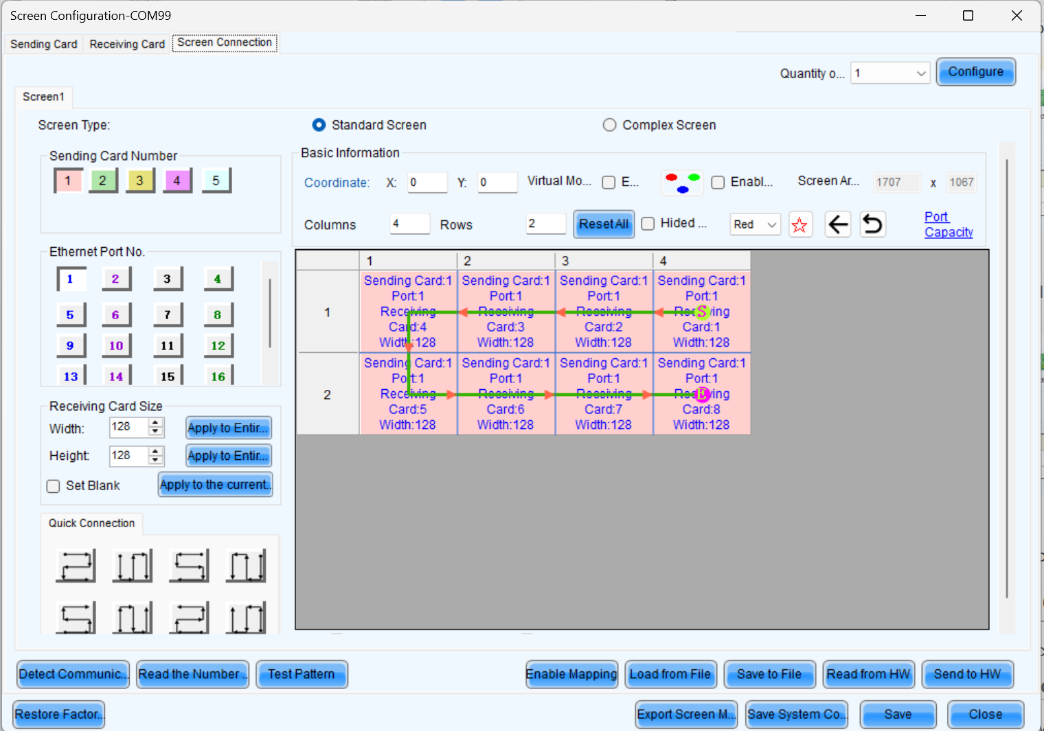
Screen connection tab
Standard Screen Connection
Click Screen configuration, then select the corresponding device IP or COM port, and click Next to enter the Screen Connection configuration interface. Take a 3x3 LED screen as an example, the resolution of a single cabinet is 480x270. As shown in the figure below.
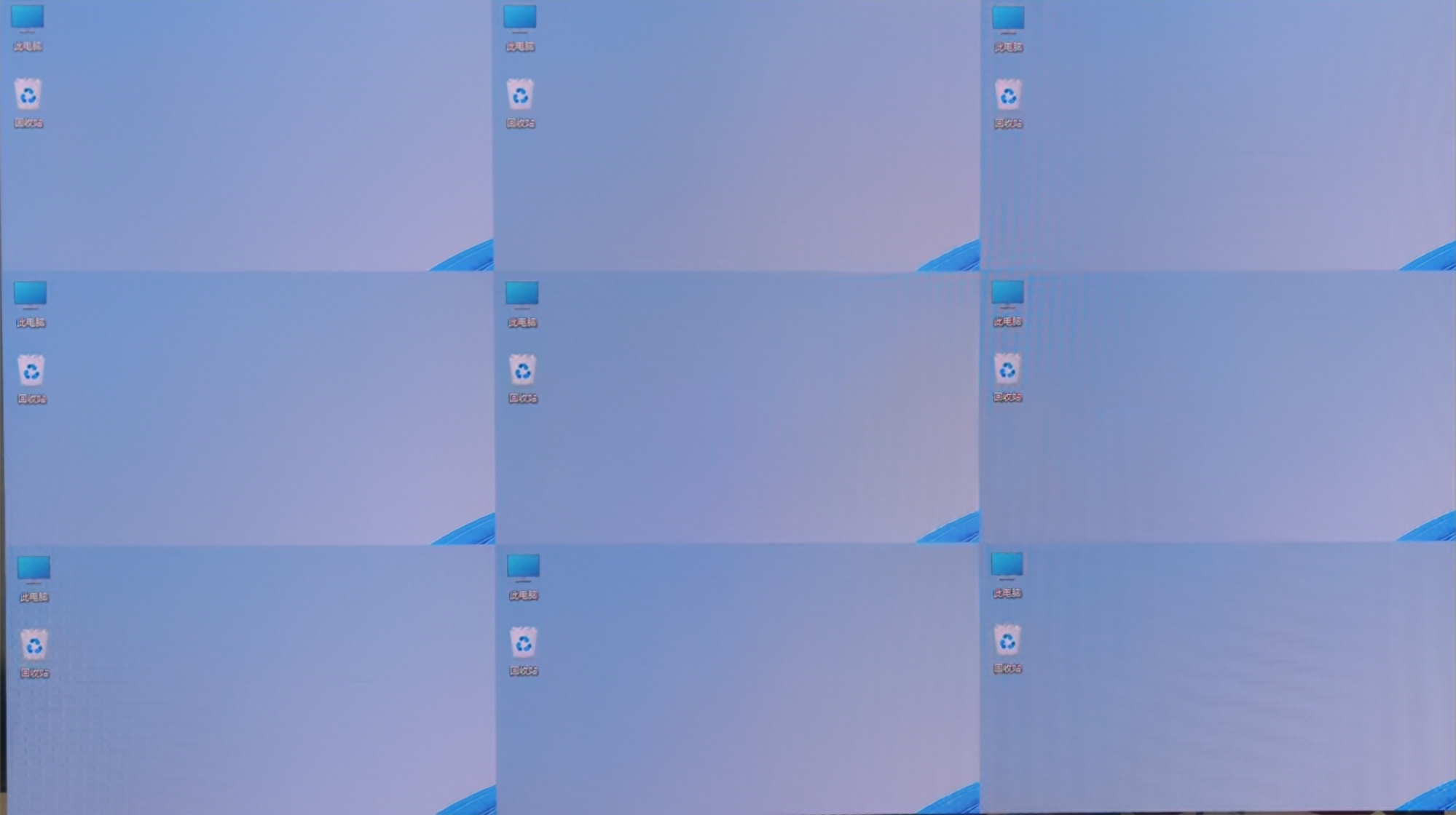
3x3 LED screen
Enable Mapping to view the physical arrangement of the cabinet.
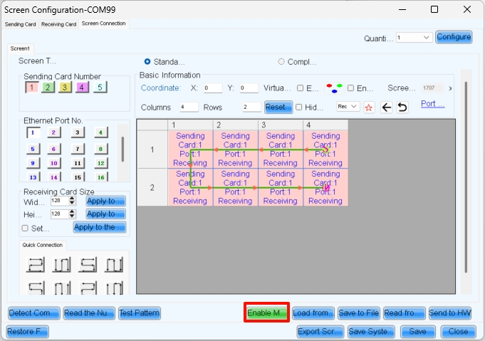
Enable Mapping
Here, S represents the sending card number, P indicates the network port number on that sending card, and # denotes the cabinet number under that port. For example, S:01 P:04 #002 means the second cabinet connected to network port 4 of the first sending card.
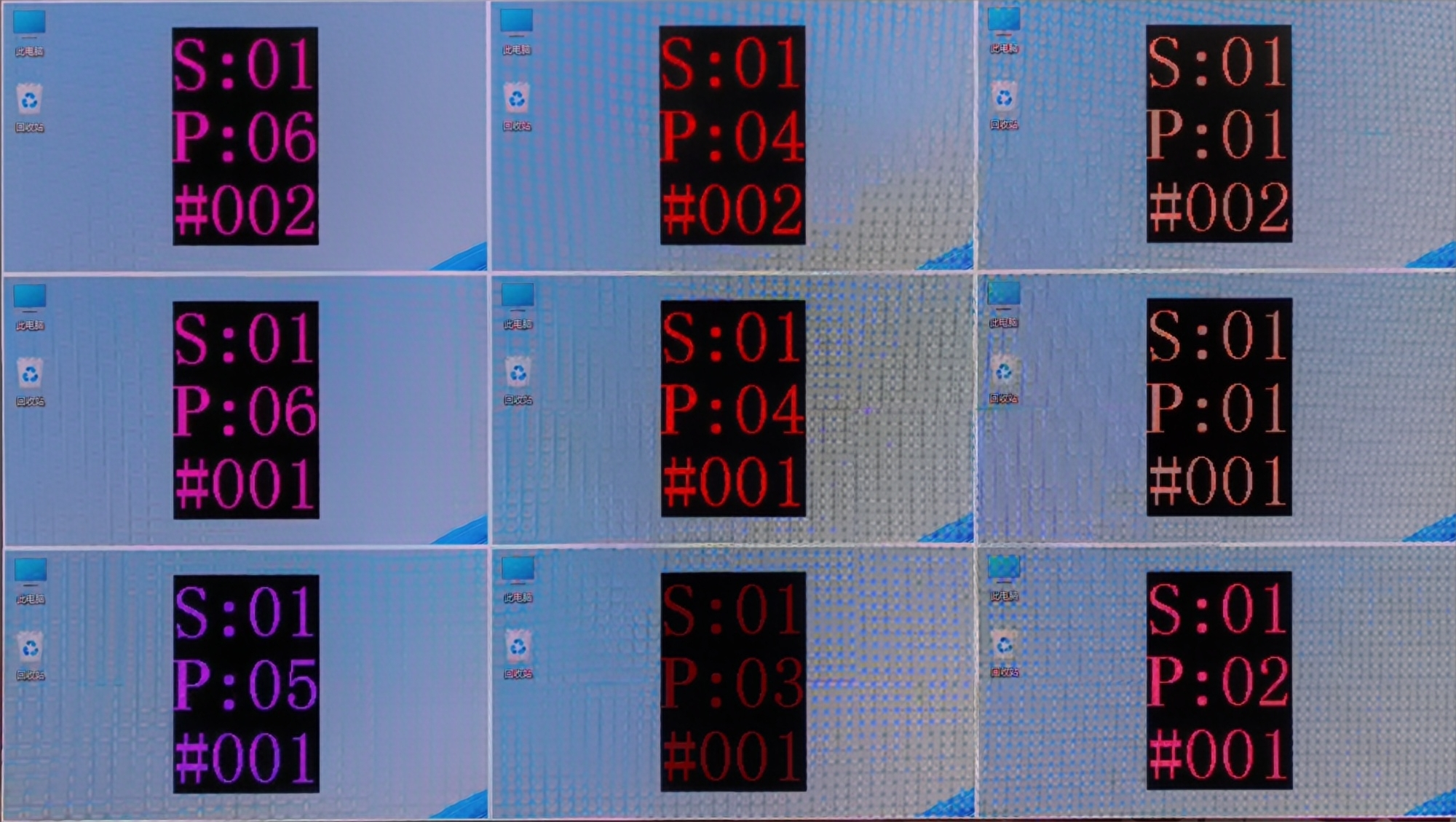
Cabinet mapping
Complete the cabinet connection according to the front view.
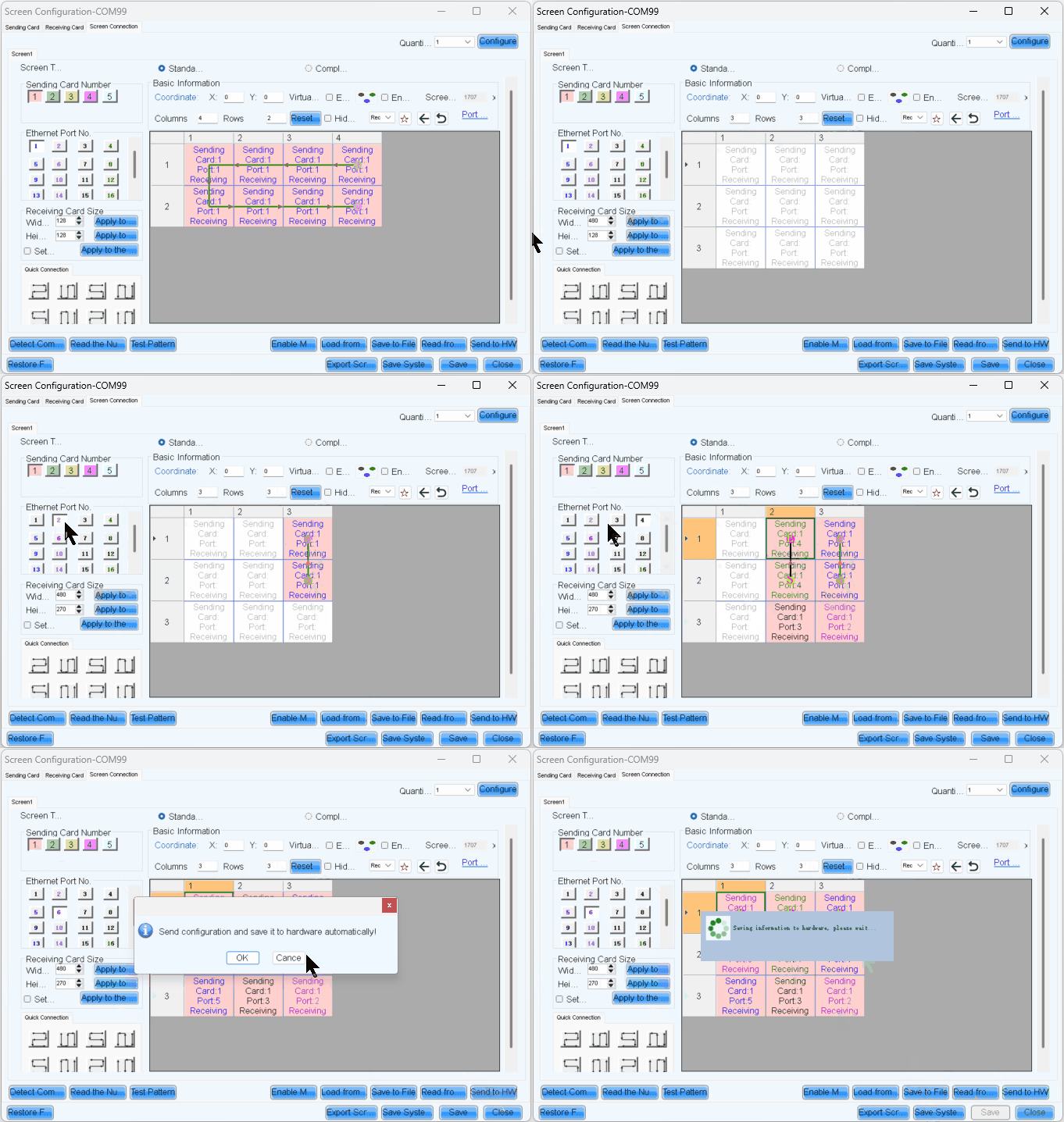
Cabinet connection
After sending and saving, the screen will display as a completed image. Then disable Mapping.
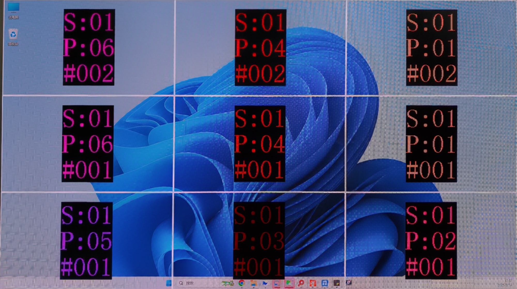
Completed screen
Complex Screen Connection
Here is an example for complex screen connection.
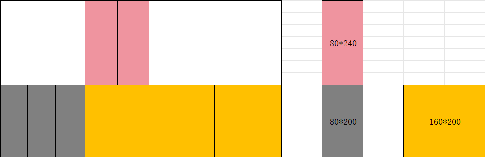
Complex screen connection example
In complex screen mode, screen connection requires coordinate settings.
⚠️ Note: Complex Screen Connection is only for devices like the MCTRL series and TB series. If your project is important and large-scale, we recommend choosing the VX PRO series and COEX series.
In the screen connection interface, select the complex screen.
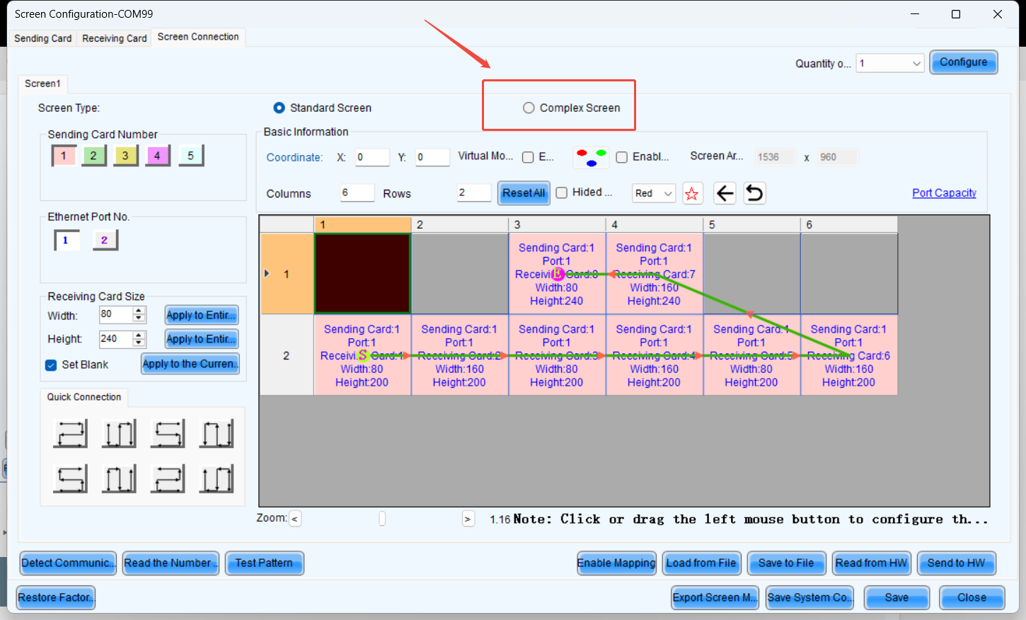
Select complex screen
Since the height of the upper half is 240 pixels, the coordinates of receiving card 1 are (0, 240). Similarly, the coordinates for receiving card 2 should increase by the width of receiving card 1 (80 pixels) along the X-axis. Therefore, the coordinates for receiving card 2 are (80, 240). The coordinate calculation logic for the remaining receiver cards remains the same as that of 1 and 2.
⚠️ Note: Complex Screen Connection still has a rectangular load limit.
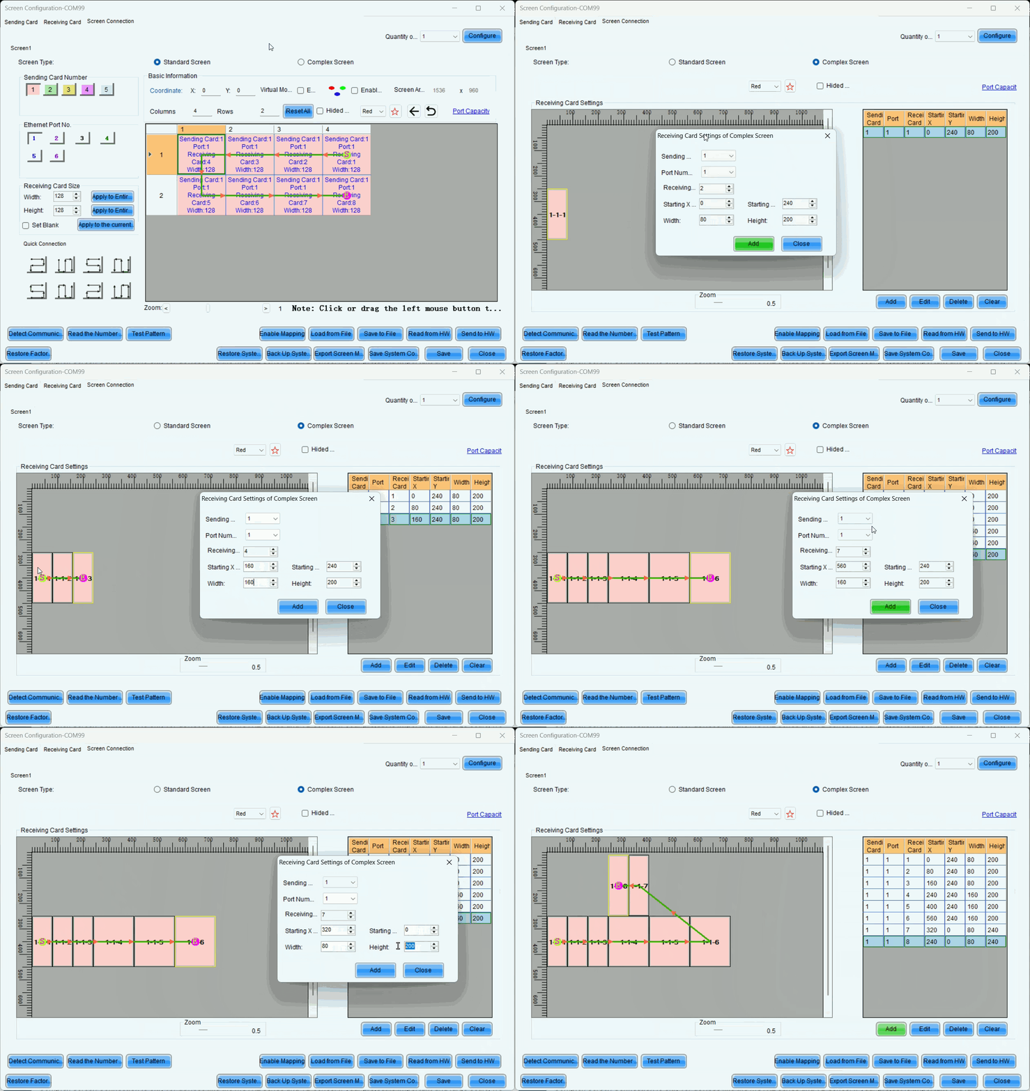
Complex screen coordinates
You also can move blocks with your mouse to align them.
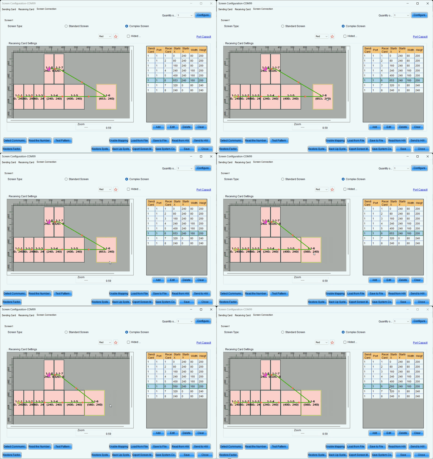
Move blocks
Troubleshooting
The second output card of the H series displayed a black screen, but the screen control was functioning normally.
- Ensure that when does H-series screen connection, each output card corresponds to one screen. For example, if we use an H2 to drive a 7680x2160 screen, with each output card handling 3840x2160, the screen connection setup would look like below, ensure that the coordinates of all output cards start from (0, 0).
- The reason is that if multiple cards are configured within a single screen, all output cards except the first one on the left will experience coordinate offset. Additionally, H web will perform a splicing operation, causing a secondary coordinate shift and resulting in black screen issues.
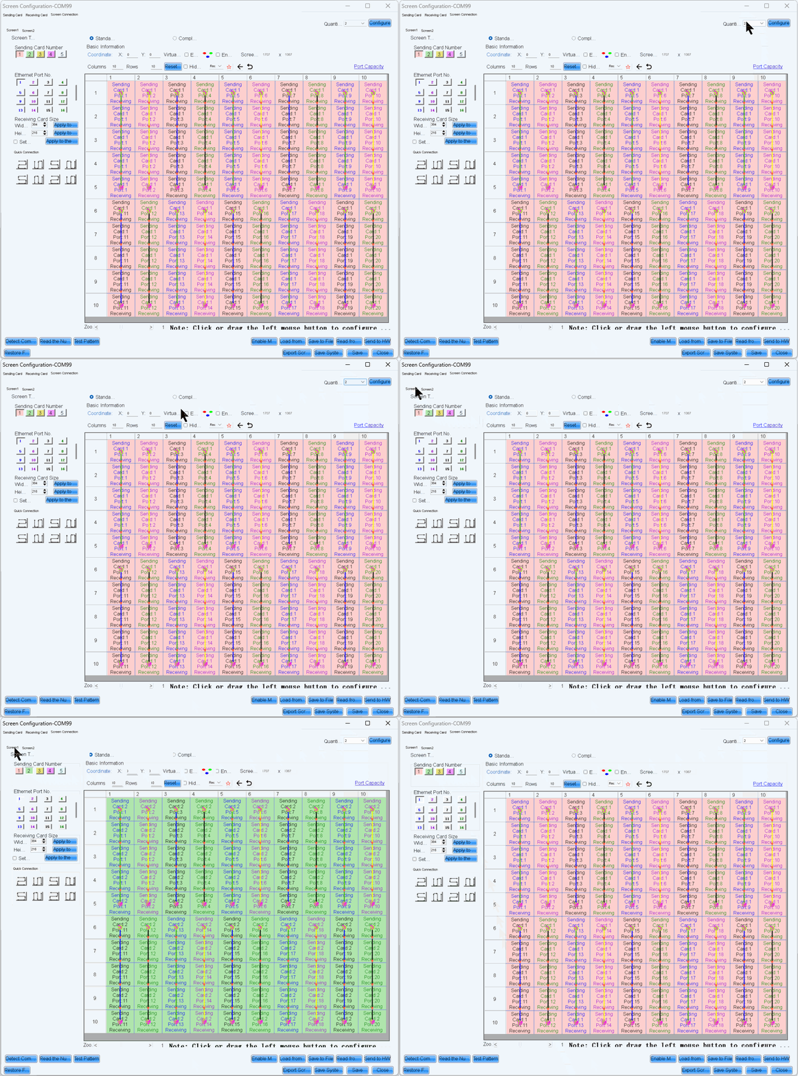
Multi-card screen connection
3. Additional features
3.1. Multiviewer Setting
The MVR card is the preview card. Ensure the MVR card is installed in the MVR card slot, then click on the MVR card in the Devices interface to edit it.
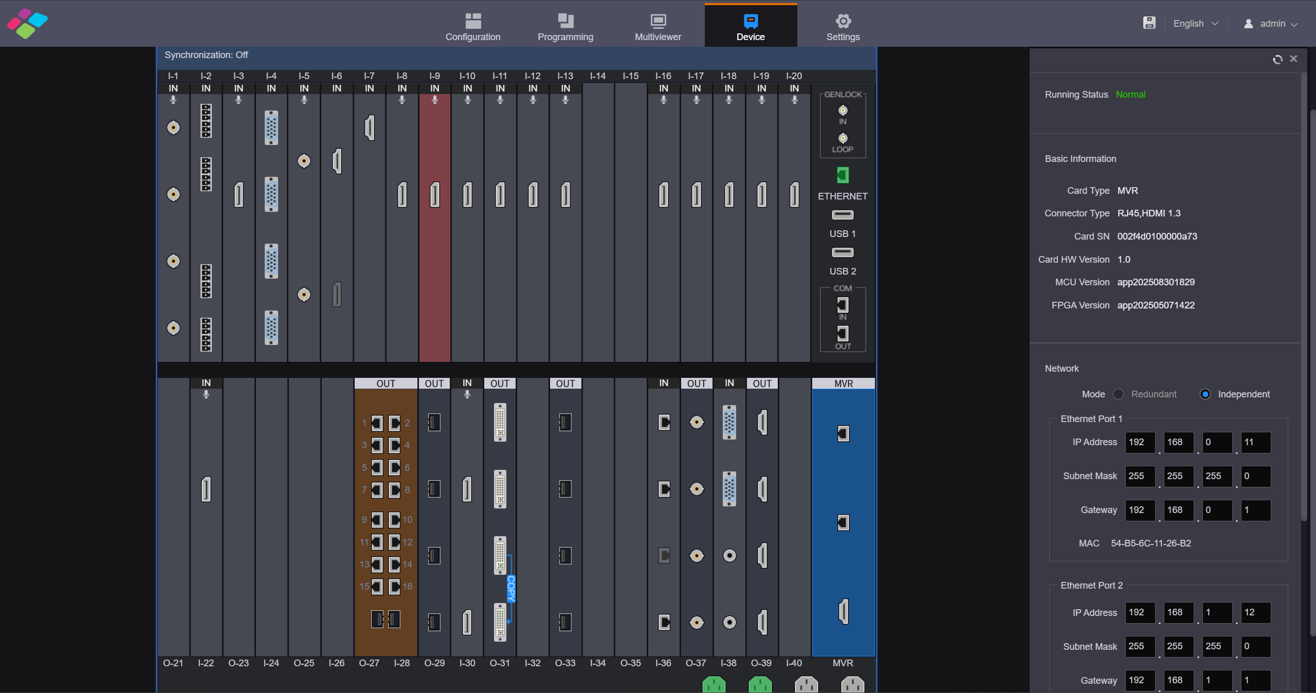
MVR card
- Running Status: Display the MVR card status.
- Normal: The card is connected normally and can be used for output.
- Abnormal: The card fails and cannot be used for output.
- Basic Information: View the basic information of the MVR card, including the card type, connector type, serial number and version number.
- Network Settings: When Ethernet ports are used for output, you need to set the IP addresses of two Ethernet ports and the URLs for the screen and input monitoring.
- Mode: Set the working mode of the Ethernet port. The working mode is independent by default, and you need to set the IP address, subnet mask and other information for each Ethernet port independently.
- IP address: Set the IP address for each Ethernet port.
- Subnet Mask: Set the subnet mask.
- Gateway: Set the gateway.
- Streaming Port: Set the Ethernet port to transmit the input monitoring data.
- Streaming Mode: When obtaining the video, select whether to prioritize Smooth or High-Definition.
- Smooth: Prioritize the playback smoothness by reducing the bitrate and resolution, suitable for scenarios with low bandwidth or high real-time requirements.
- High-Definition: Prioritize the image clarity by using high bitrate and resolution, suitable for scenarios with good network conditions and high demands for image quality.
Layer Capacity (Multiviewer)
- Per output card (H15 example): Up to 16 2K layers per card on the H15 (standard), or 10 layers on the H15 (enhanced). Layer size trade-offs: 8 DL layers, 4 4K layers or 2 8K layers.
- Cross-connector layers: Layers can span across connectors without reducing the layer count.
- Scene switching: When the sum of layer resources of the current and target scenes exceeds 16, the switch is forced to a direct cut (no fade in/out).
- Preset templates: 4 common monitoring templates are preconfigured; custom templates are supported.
- Model differences: Layer capacity varies by model (H5, H20, etc.) — refer to the corresponding model's datasheet.
3.2. 3D Setting
The H series can work with the EMT200 Pro 3D emitter from NovaStar and 3D glasses to provide you with 3D visual experience. You can set the 3D parameters in NovaLCT or on the Web.
⚠️ Note:
- Turning on 3D mode will halve the device output capacity.
- The 3D and low latency functions cannot be turned on at the same time.
- For pixel-to-pixel display in 3D mode, if the 3D source is in side-by-side format, the layer width must be set to half of the input source width; if the 3D source is in top-and-bottom format, the layer height must be set to half of the input source height.
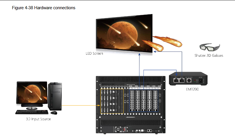
EMT200 Pro connection
The EMT200 Pro is connected in between the LED 4K sending card and the receiving card via Ethernet cables, or connected to any of the receiving cards. Each screen supports only one EMT200 Pro.
3D Settings on Webpage
- Step 1: Click Configuration to enter the screen configuration page.
- Step 2: Select the desired screen.
- Step 3: Click on the right side to expand the screen parameter configuration pane.
- Step 4: Click the Basic Info tab.
- Step 5: Check the box next to 3D to enable the 3D function.
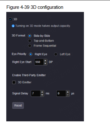
3D on Webpage
- Step 6: Select the video source format. The supported options include Side-by-Side, Top-and-Bottom and Frame Sequential.
- Step 7: Set the eye priority according to the 3D glasses mode. The supported options include Left eye and Right eye.
- Step 8: Set the right eye start position.
⚠️ Note:
- For side-by-side 3D sources, Right Eye Start must be set to half of the input source width.
- For top-and-bottom 3D sources, Right Eye Start must be set to half of the input source height.
- For frame sequential 3D sources, Right Eye Start cannot be set.
- Step 9: Select or unselect 3D Emitter according to your actual setup.
- Step 10: Adjust the signal delay time to make left and right eye images of the 3D glasses in sync with the images on the display.
3D Settings in NovaLCT
- Step 1: Log in to NovaLCT.
- Step 2: Go to Screen Configuration > Sending Card to open the sending card window.
- Step 3: Check the box in front of Enable to turn on the 3D function.
- Step 4: Click Set 3D Parameters to open the 3D parameter settings window.
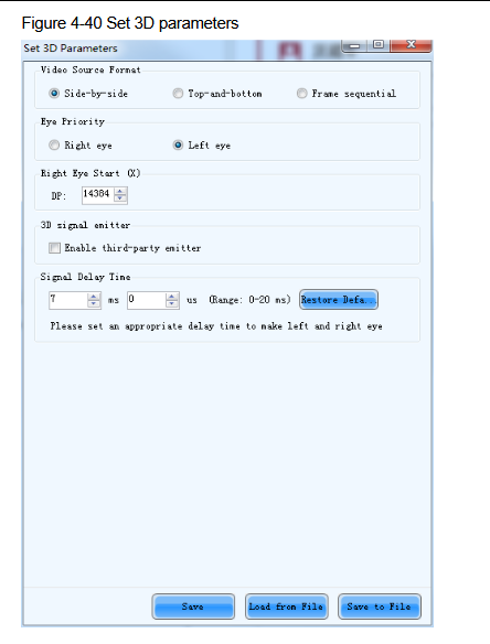
3D in NovaLCT
- Step 5: Select the video source format. The options are Side-by-Side, Top-and-Bottom and Frame Sequential.
- Step 6: Set the eye priority according to the 3D glasses mode. The options are Left eye and Right eye.
- Step 7: Set the right eye start position.
⚠️ Note:
- For side-by-side 3D sources, Right Eye Start must be set to half of the input source width.
- For top-and-bottom 3D sources, Right Eye Start must be set to half of the input source height.
- Step 8: Select or unselect Enable third-party emitter according to your actual setup.
3D Notes
- 100Hz 3D is also supported: In this mode, set the H output frame rate to 50Hz.
- Signal delay time: Adjustable from 0 to 20ms to keep the 3D glasses in sync with the display switching.
- Extending coverage with EMT100: A third-party emitter EMT100 can be connected to the EMT200 Pro via the EXT 3D SYNC interface. It supports up to 100 pairs of MX50 glasses and a range of up to 70m.
- Only one EMT200 Pro per site: Otherwise the glasses may switch between multiple emitters and affect the 3D effect.
- Frame-sequential sources: Left/right eye effects may become abnormal after device restart or re-plugging of the signal source — switch the left/right eye priority again.
- Loading reference: Refer to K16 screen configuration. A single 16-port 2-in-1 output card can load up to 5.2M pixels in 3D mode; a 20-port card up to 6.5M pixels.
3.3. HDR
HDR is the abbreviation for High-Dynamic Range. HDR function can greatly enhance the display image quality, allowing for a clearer and vivid image when the device is used together with NovaStar A8s/A10s receiving cards.
Select HDR to enable the HDR function.
- Format: Select the format of the current HDR source. HDR10 and HLG are both supported. HDR10 is selected by default.
- Peak Screen Brightness: Adjust the screen brightness under normal operation. The value ranges from 100 to 10000 and defaults to 1000.
- Ambient Illuminance: Display the ambient illuminance. The value ranges from 0 to 200 and defaults to 30.
- Low Grayscale Mode: Adjust the screen image grayscale. The value ranges from 0 to 50 and defaults to 15.
HDR Notes
- Prerequisites: The receiving cards must support HDR (e.g. A8s / A10s Plus) and be connected normally. The receiving card brightness and color coordinates must have been calibrated.
- Source requirement: The input signal itself must be HDR10 or HLG to achieve the HDR display effect.
- Loading impact: HDR sources are 10bit. Enabling HDR halves (or reduces by a quarter, depending on configuration) the device loading capacity — plan the wiring accordingly.
- Connector limit: HDR sources can only be connected to the HDMI 2.0 connector (12G-SDI on some models).
- Mutual exclusions: HDR cannot be used together with 3D, nor together with the loading capacity expansion function.
- DP1.2 sub-cards do not support HDR: When using a media server with the H series, note that DP1.2 sub-cards cannot output HDR.
3.4. Preset & Preset Playlist
After completing the layer settings, you can save the edited content as a "preset," allowing multiple presets to cover different usage scenarios.
- Step 1: On the Programming page, click Save Preset below the layer editing area to open the preset saving window.
Save Preset
- Fill in the scene name according to actual needs.
- Click "Save" to complete the scene saving.
- Click "Preset" on the left to open the scene list and manually switch between different scenes.
Preset switching
- The preset playback function allows you to play the presets automatically based on the set playback sequence and single preset playback duration. After the settings, the system will play the presets automatically with no manual operations required. On the Programming page, click Preset Playlist on the left to enter the preset playlist settings page.

Set Preset Playlists
3.5. H Audio Setting
When H series device is installed with H_2xAudio input+2xAudio output card, the audio output is supported. When the audio adapter wiring is required, please refer to A Audio Adapter Wiring to complete the audio connector connection.
- Step 1: Click Programming to enter the programming page.
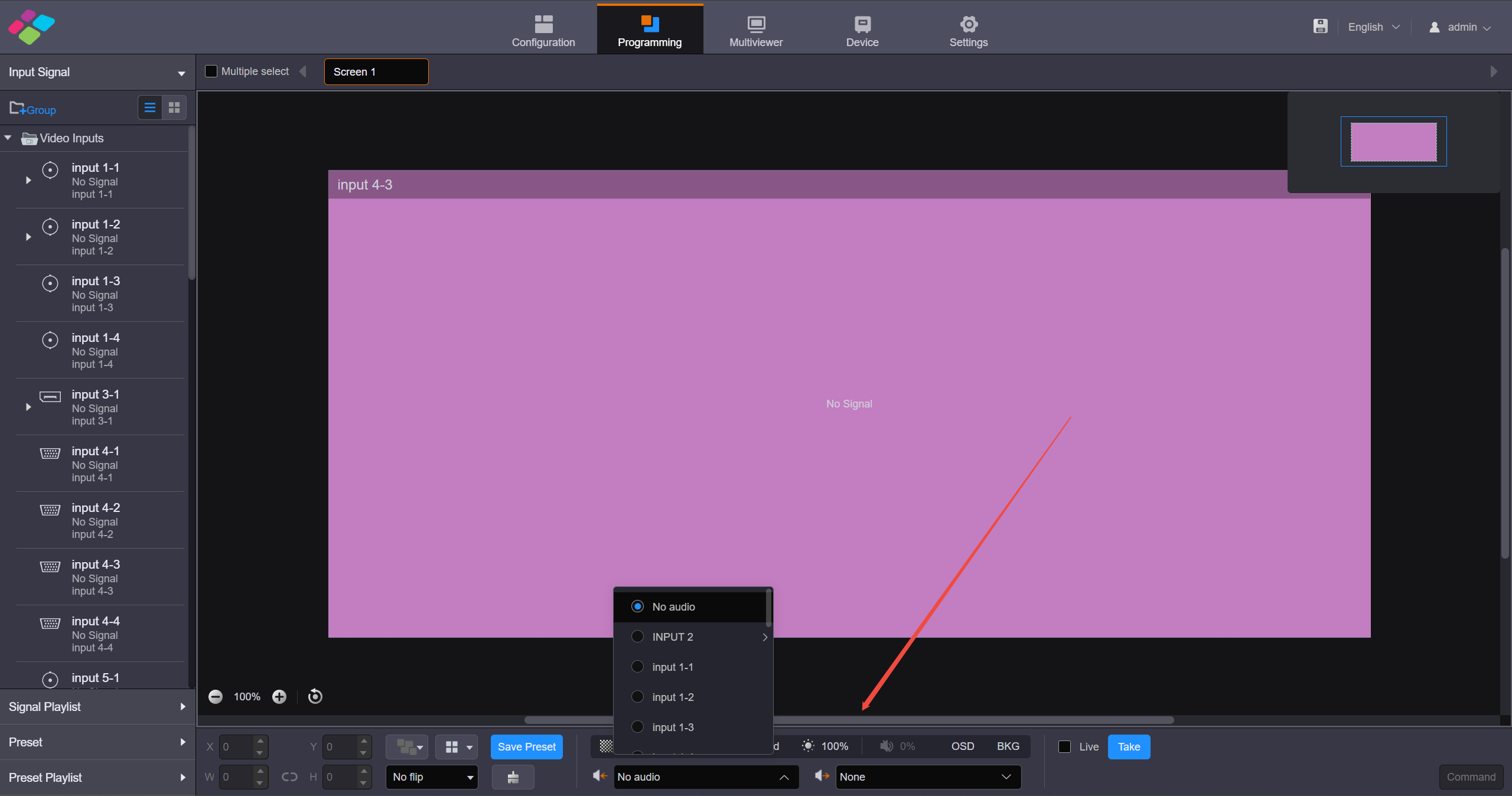
Set input and output audio
- Step 2: Set the input audio. Click the dropdown box to the right of the audio input icon in the lower right corner and select the audio input source. Supported options include audio from the sound card input interface or accompanying audio from the HDMI input interface.
- Step 3: Set the output audio. Click the dropdown box to the right of the audio output icon in the lower right corner and select the audio output interface. The sound card output interface is supported for audio output.
3.6. Backup Management
Click Backup Management on the left to enter the backup management page. You can save and export the configured device parameters as a configuration file for future use.
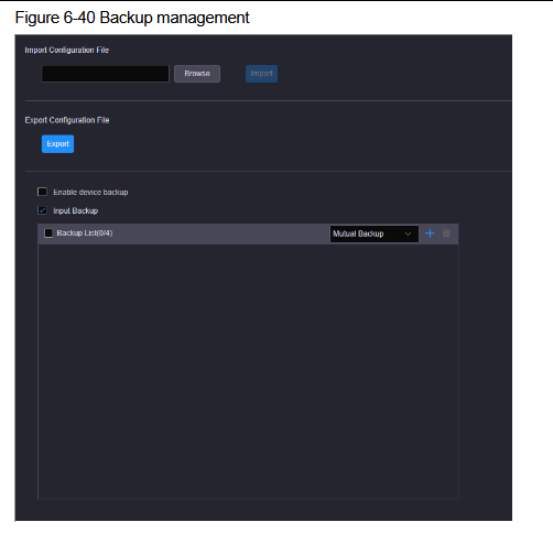
Backup Management
Import/Export Configuration Files
- Import Configuration File: Import the saved configuration file for quick screen configuration, color, EDID, layer, BKG, OSD, preset and preset playback settings.
- Export Configuration File: Click Export to export the device configuration parameters for future use.
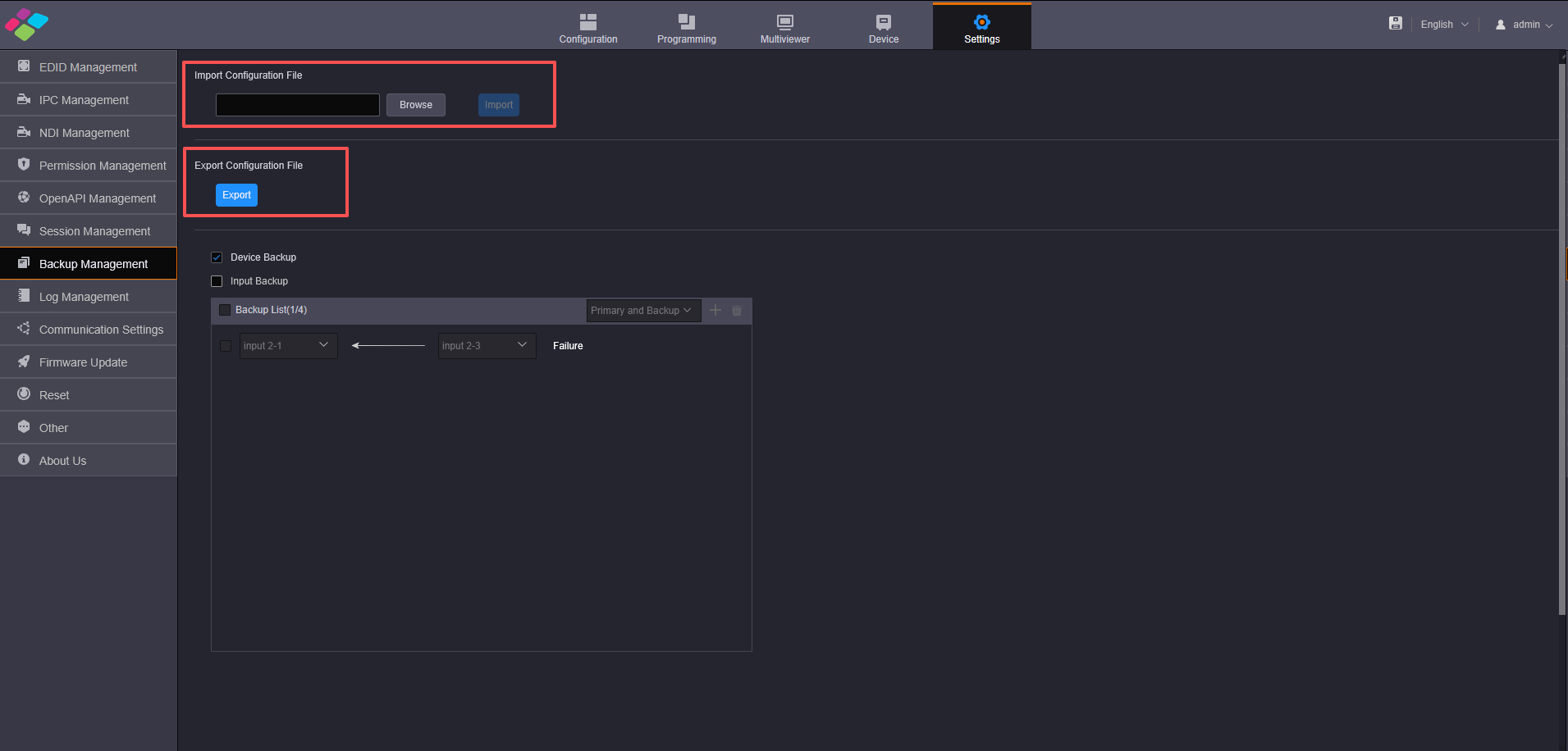
Import/Export
Device Backup
- When both the primary and backup sources fail, the device backup will take effect.
- The H series devices support both the backup between the devices and the backup between the sending cards on the same device. You must set the backup in NovaLCT by referring NovaLCT User Manual.
- After configuring the backup in NovaLCT, on the Backup Management page of each device, check the box in front of Enable device backup to turn on the backup function.
- If you connect the H series device via NovaLCT, the controlled sending card varies depending on the communication port. The correspondence between the communication port and sending card is shown in the following table.
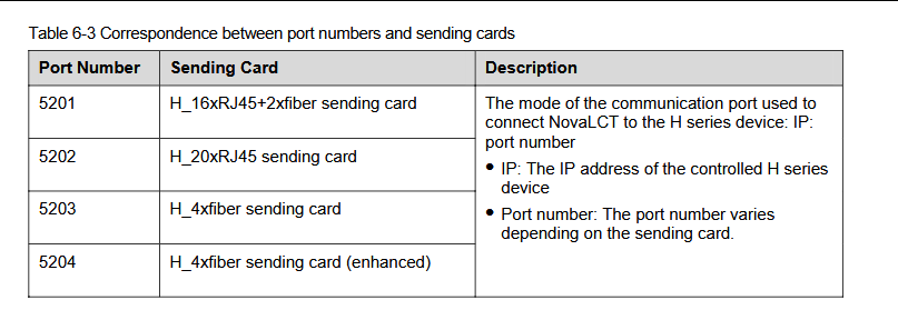
Communication port correspondence
The backup between cards refers to the backup relationship between two sending cards of the same type on the same device.
- Step 1: Run the NovaLCT software. On the menu bar, go to User > Advanced Synchronous System User Login.
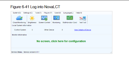
Log in to NovaLCT
- Step 2: Click Screen Configuration to open the window.
- Step 3: Select a communication port and click Next to open the Screen Configuration window.
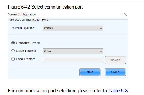
Screen Configuration window
- Step 4: Click the Sending Card tab and set the backup relationship between two sending cards in the Redundancy area.
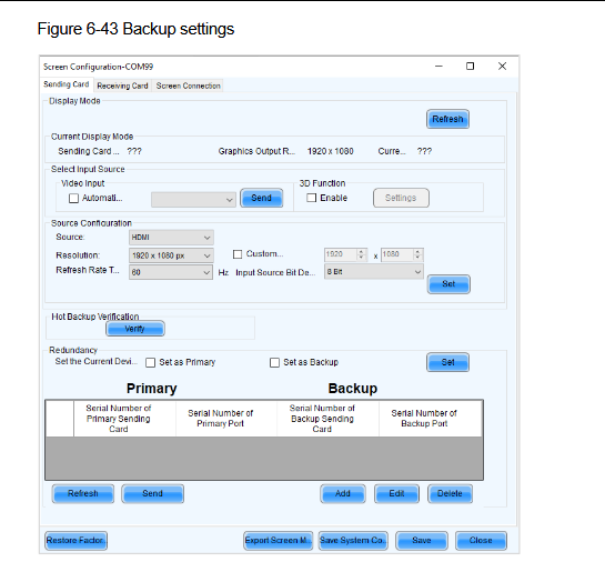
Sending Card tab
There are two methods to set the backup relationship between two sending cards.
Configure the backup relationship between connectors.
a. In the Redundancy area, click Add to open the Redundancy Settings window.
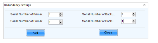
Redundancy Settings
b. Enter the serial numbers of the primary sending card, primary port, backup sending card and backup port respectively. If you set the backup relationship between the Ethernet ports on the same sending card, enter the same serial numbers of both the primary and backup sending cards. If you set the backup relationship between the Ethernet ports on different sending cards, enter the serial numbers of both the primary and backup sending cards according to the device cascading relationship. c. Click Add to complete the backup relationship settings. d. Repeat the above mentioned operations to set the backup relationship of other connectors. Click Close to complete the settings. e. Click Send to send the configuration to the H series device. f. Click Save to save the configuration to the H series device.
Configure the backup relationship between two sending cards.
a. In the Redundancy area, click Set to open the Redundancy settings window.
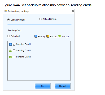
Set Redundancy
b. Click Set as Primary. c. In the sending card list, select the desired sending card used as the primary one. d. Click Set to complete the primary card settings. e. Click Set as Backup. f. In the sending card list, select the desired sending card used as the backup one. g. Click Set to complete the backup card settings. After you set both the primary and backup sending cards, the status icons of Primary and Backup will be displayed next to the corresponding cards.
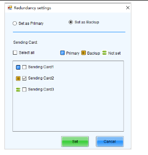
Primary and Backup status
h. After you complete the settings, click Save to send the configuration to the H series device.
- Step 5: After you complete the backup settings, click the Screen Configuration tab to open the corresponding window.
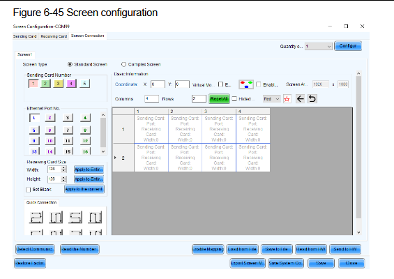
Screen Configuration tab
- Step 6: Select the desired screen quantity from the drop-down list next to Quantity of Screens, and then click Configure to complete the configuration. You can also increase or decrease the screen quantity here.
Screen quantity descriptions:
-
When you set the backup relationship between Ethernet ports, only one screen loaded by the primary Ethernet ports needs to be configured.
-
When you set the backup relationship between sending cards, you need to configure the screen for each sending card, and the screen configuration parameters of the primary and backup cards must be the same. The screen configuration parameters include the screen size, cabinet size and connection topology of the Ethernet ports matched with the primary and backup sending cards.
-
Step 7: Configure the loaded screen.
- Set the cabinet width and height in the Receiving Card Size area according to the actual cabinet specification.
- Set the values of Columns and Rows of the receiving card.
- Select the desired sending card number and Ethernet port number respectively.
- Set the connection topology of the receiving card.
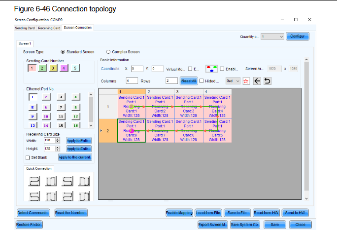
Configure loaded screen
- Repeat the above mentioned two steps to complete the connection topology of other ports. When you set the backup relationship between two sending cards, you need to configure another screen whose connection topology is the same as that of the primary sending card.
- After you complete the configuration, click Send to HW to send the configuration to the H series device.
- Click Save to save the configuration to the hardware.
Device Backup (between two devices)
Set the backup relationship between two devices.
- Step 1: Go to Settings > Backup Management to enter the backup management page.
- Step 2: Check the box next to Enable Device Backup.
- Step 3: Run the NovaLCT software. On the menu bar, go to User > Advanced Synchronous System User Login.
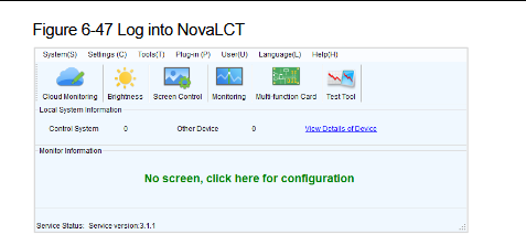
NovaLCT login
- Step 4: Click Screen Configuration to open the window.
- Step 5: Select a communication port and click Next to open the Screen Configuration window.
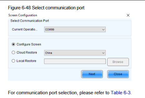
Select communication port
- Step 6: Click the Sending Card tab and set the backup relationship between two devices.
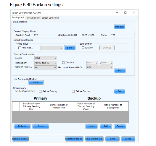
Device backup setting
- Step 7: If the current device serves as the primary one, check the box next to Set as Primary.
- Step 8: Repeat Step 3 to select the communication port of the backup device, and then the backup device will be connected.
- Step 9: In the Redundancy area, check the box next to Set as Backup.
- Step 10: On the Screen Configuration page, configure the screen loaded by the primary and backup devices respectively. The screen parameters of the primary device must be the same as that of the backup device.
⚠️ Note: The settings for the backup device and the backup sending card must be same as that of the primary device and primary sending card.
Input Backup
The H series devices support the input source backup function. If the input signal in use is abnormal or lost, the backup one will take over the job seamlessly to ensure the display not go black. The backup relationship cannot be set for NDI or IPC sources.
- Step 1: Click Backup Management on the left to enter the backup management page.
- Step 2: Check the box next to Input Backup to enable the input source backup function.
- Step 3: Select the desired backup relation. The options include Mutual Backup and Primary and Backup.
- Mutual Backup: When one input source fails, the other one takes the job seamlessly; when the failed one resumes, it continues to work normally and the other does not work.
- Primary and Backup: When the primary input source fails, the backup one takes the job seamlessly; when the primary one resumes, it continues to work normally and the backup one does not work.
- Step 4: Click + symbol at the top right of the input backup list to add a new backup pair.
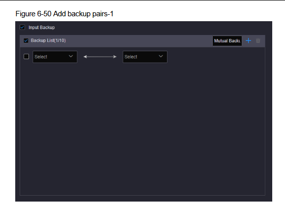
Add backup pair
- Step 5: Select two input sources respectively from the two drop-down lists to complete the adding of one backup pair.
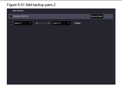
Select input sources
The system will automatically detect the status of the backup one and display the status next to the backup pair.
- Step 6: Repeat Step 4 and Step 5 to add more backup pairs.
3.7. Brightness Setting
One-time brightness adjustment on Webpage
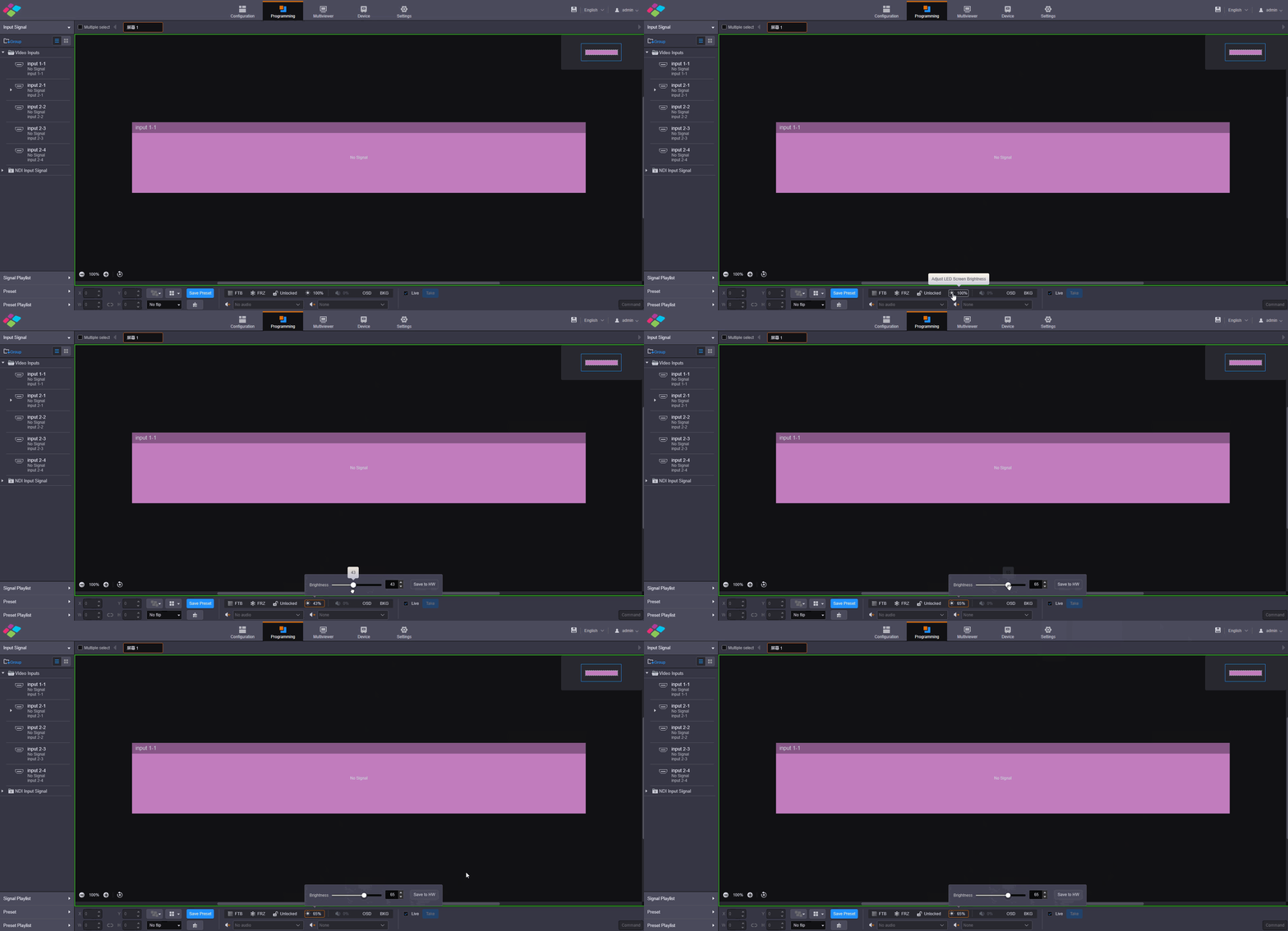
One-time brightness on web
One-time brightness adjustment on Front LCD Screen
The H series device supports the control of the added screen via the front panel LCD, including loading presets, adjusting screen brightness, turning on/off OSD and switching 3D eye priority.
- Step 1: Go to Settings > Screen to enter the screen control screen.
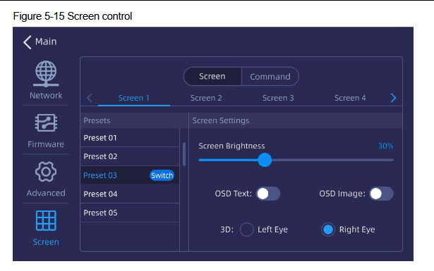
Screen control
- Step 2: Select the Screen tab.
- Step 3: Select the desired screen and you can perform the following operations.
- Load a preset: Select the desired preset from the preset list on the left, and click Switch to load the selected one.
- Adjust screen brightness: When the loaded screen is an LED screen, the screen brightness adjustment is supported. You can drag the slider to adjust the brightness.
- Enable OSD text: When the OSD text is configured on the screen, you can turn on/off the toggle switch next to OSD Text to enable/disable the OSD text.
- Enable OSD image: When the OSD image is configured on the screen, you can turn on/off the toggle switch next to OSD Image to enable/disable the OSD image.
- 3D: When the 3D function is enabled, select Left Eye or Right Eye to switch the eye priority according to the mode of the 3D glasses.
Smart Scheduled Brightness Adjustment
When the device is used to load an LED screen, the system will automatically adjust the screen brightness according to the set time and brightness value.
You need to select the adjustment mode according to the used module chip.
-
Common: Except for the 2153 module chip, other chips not used for special adjustment.
-
Special: Only for the 2153 module chip.
-
Step 1: Go to Settings > Other to enter the other settings page.
-
Step 2: In the Smart Brightness Adjustment area, select the adjustment mode according to the used module chip.
-
Step 3: Select the desired screen from the drop-down list.
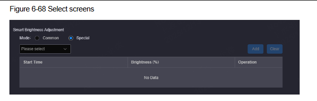
Smart brightness adjustment
- Step 4: Click Add to open the brightness adjustment settings window.
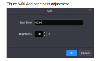
Add brightness adjustment
- Step 5: Set the adjustment start time.
- Step 6: Set the target brightness value. The value ranges from 0 to 100.
- Step 7: Click OK to complete the adding.
- Step 8: Repeat Step 4 to Step 7 to add new adjustment.
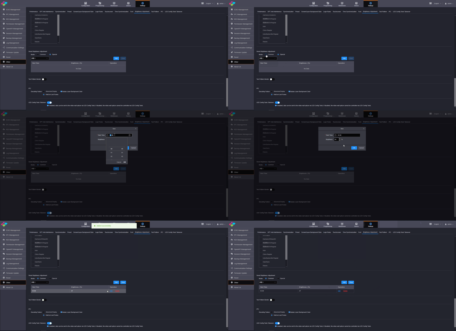
Brightness schedule
3.8. H web Other Functions
On this page, you can set the performance, Genlock and preset transition.
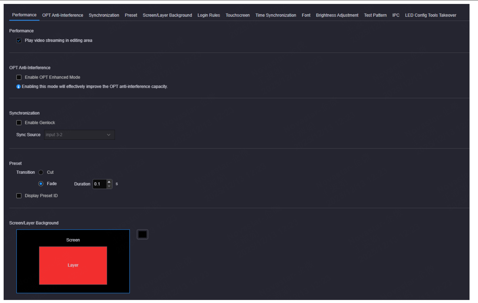
Other functions
Performance
Set whether to play the video streaming of the layer in the editing area. Turn off this function for quicker layer configuration.

Performance
OPT Anti-Interference
Enable or disable the OPT anti-interference function of the H_4xfiber sending card and H_16xRJ45+2xfiber sending card.
- Select Enable OPT Enhanced Mode to enable the OPT anti-interference function. Once enabled, the H series device must work with the CVT10 and CVT4K of V1.3.0 or later to ensure normal output.
- Deselect Enable OPT Enhanced Mode to disable the OPT anti-interference function. Once disabled, the H series device can work with fiber converters or video controllers that support OPT input to ensure normal output.
- If the OPT anti-interference function is enabled, but the backend device does not support this function, the image cannot be output normally.
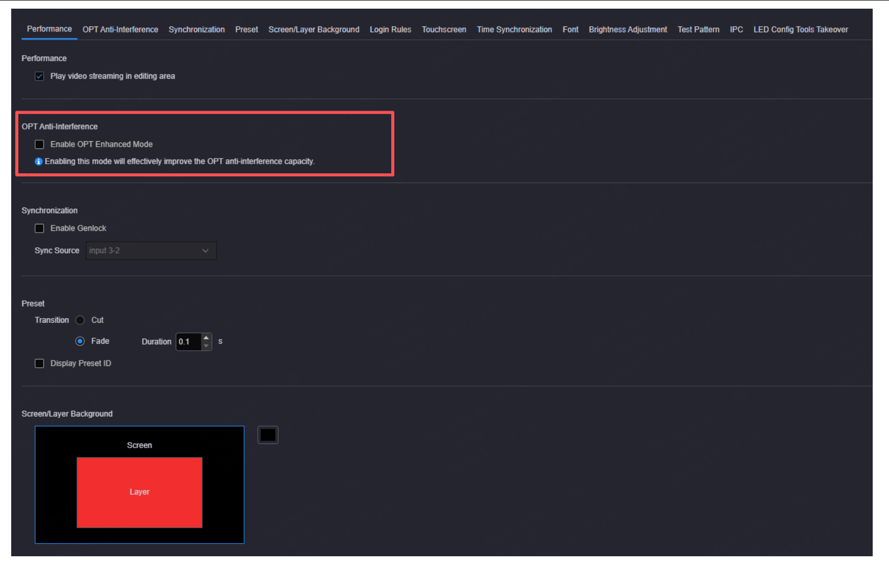
OPT anti-interference
Synchronization
- Enable Genlock: Set whether to use the external Genlock sync source.
- Select Enable Genlock to turn on the Genlock function.
- Deselect Enable Genlock to turn off the Genlock function.
- Sync Source: Select the connected input source used as the sync source.
⚠️ Note:
- When you use an input source for synchronization, the synchronization will be successful if the difference value between the frame rate of the sync source and the output frame rate (not SDI connector) is within ±0.5%.
- The synchronization will be successful if the difference value between the refresh rate of the sync source and the output refresh rate of the SDI connector is within ±0.01%.
- The supported sync refresh rate of the SDI connector: 23.98/24/25/29.97/30/50/59.94/60Hz.
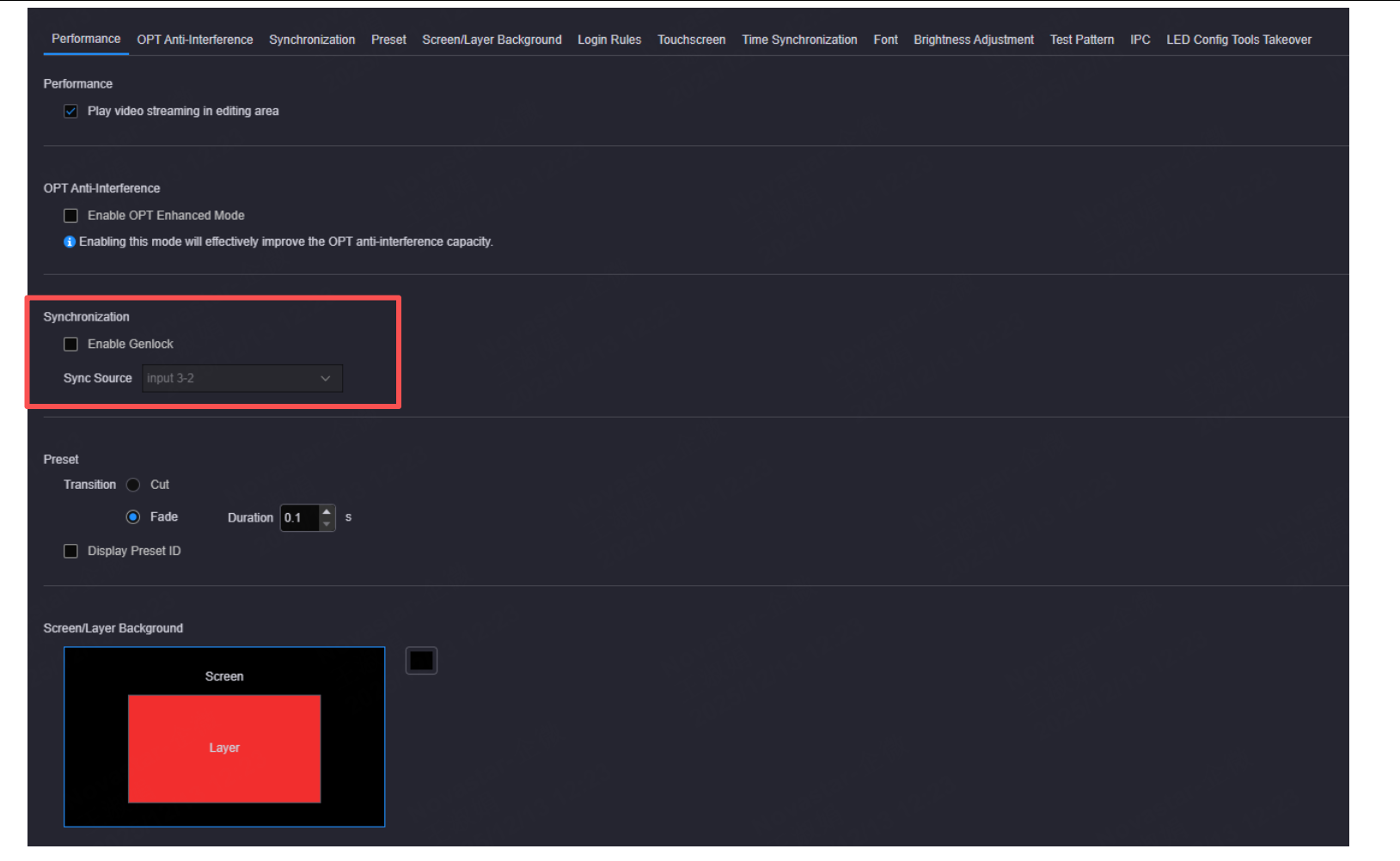
Synchronization
Preset Transition
Set the preset transition effect. Cut and fade effects are supported. When Fade is selected, the transition duration can be set.
⚠️ Note:
- If the total number of the layers in the current preset and the preset to be switched exceeds 16x SL layers, 8x DL layers, 4x 4K layers or 2x 8K layers, the fade effect is not supported and the preset will be switched in cut mode.
- The screens loaded by the H_4xfiber sending card, H_4x3G SDI output card, H_1x12G SDI output card and H_4xHDBaseT output card do not support the fade transition effect.
- The screen loaded by the H_4xfiber sending card (enhanced) supports the fade transition effect.
Check the box next to Display preset ID and the system will automatically add an ID for each added preset. The preset ID contains four digits and is displayed in front of the preset name. Once enabled, it will be added automatically by the system and cannot be changed.
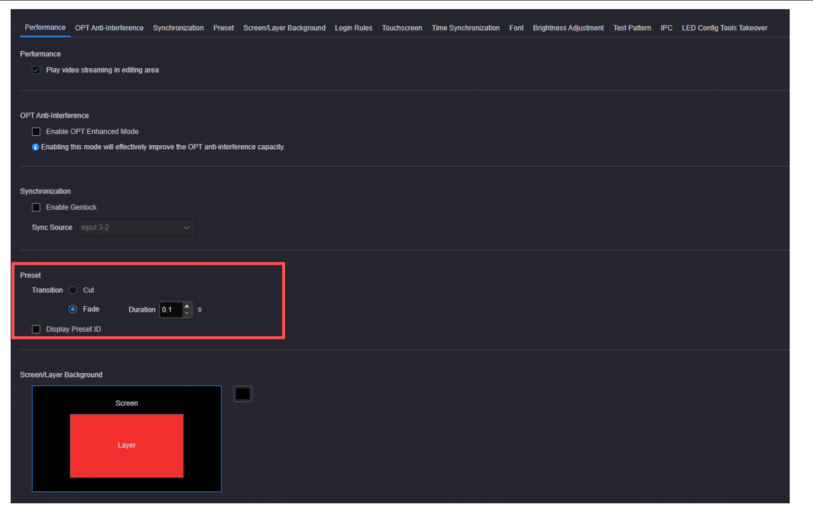
Preset transition
Set Screen Background
- Step 1: Click the screen area to select the screen. After selection, the screen border is highlighted in blue.
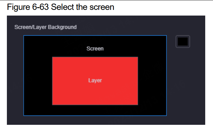
Set screen background
- Step 2: Click the color picker at the top right corner.
- Step 3: Select the desired color or enter the R, G, and B values to customize your own color.
Set Layer Background
- Step 1: Click the layer area to select the layer. After selection, the layer border is highlighted in blue.
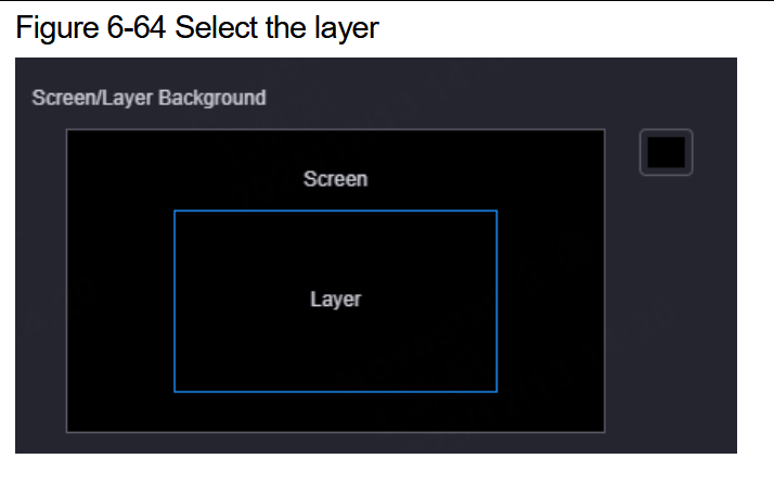
Set layer background
- Step 2: Click the color picker at the top right corner.
- Step 3: Select the desired color or enter the R, G, and B values to customize your own color.
Login Rules
Set the expiration mode and time after the user logs in to the Web page.
- Expiration Mode: Set the expiration mode when the login has expired. The supported options include Never, Fixed and Sliding.
- Never: The login is long-term valid with no need to log in to the system again.
- Fixed: Set the expiration time. If the login time exceeds the set time, the login will automatically expire and the user needs to log in to the system again for operations.
- Sliding: Set the expiration time. If no operation is made during the set time, the login will automatically expire and the user needs to log in to the system again for operations.
- Expiration Time: Set the default login time. The default value is 30 minutes.
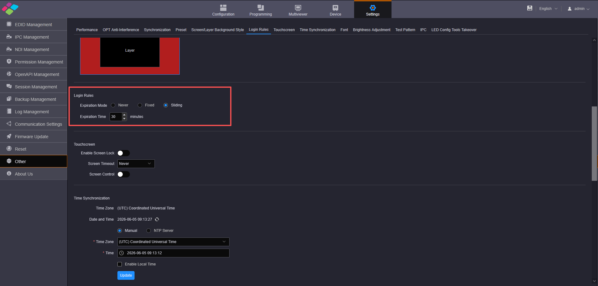
Login rules
Touchscreen
- Enable Screen Lock: Enable or disable the screen lock function. Once enabled, the lock icon will be displayed on the front panel LCD and no operation is allowed on the LCD screen.
- Screen Timeout: Set the period time after which the screen will automatically turn off when no operation is performed. The supported options include 30s, 60s, 120s, 300s and Never. Never: The screen always stays on and displays the corresponding content.
- Screen Control: Enable or disable the screen control function.
⚠️ Note: Before enabling or disabling the desired function below Touchscreen, you need to enter the correct device login password in the popup dialog.
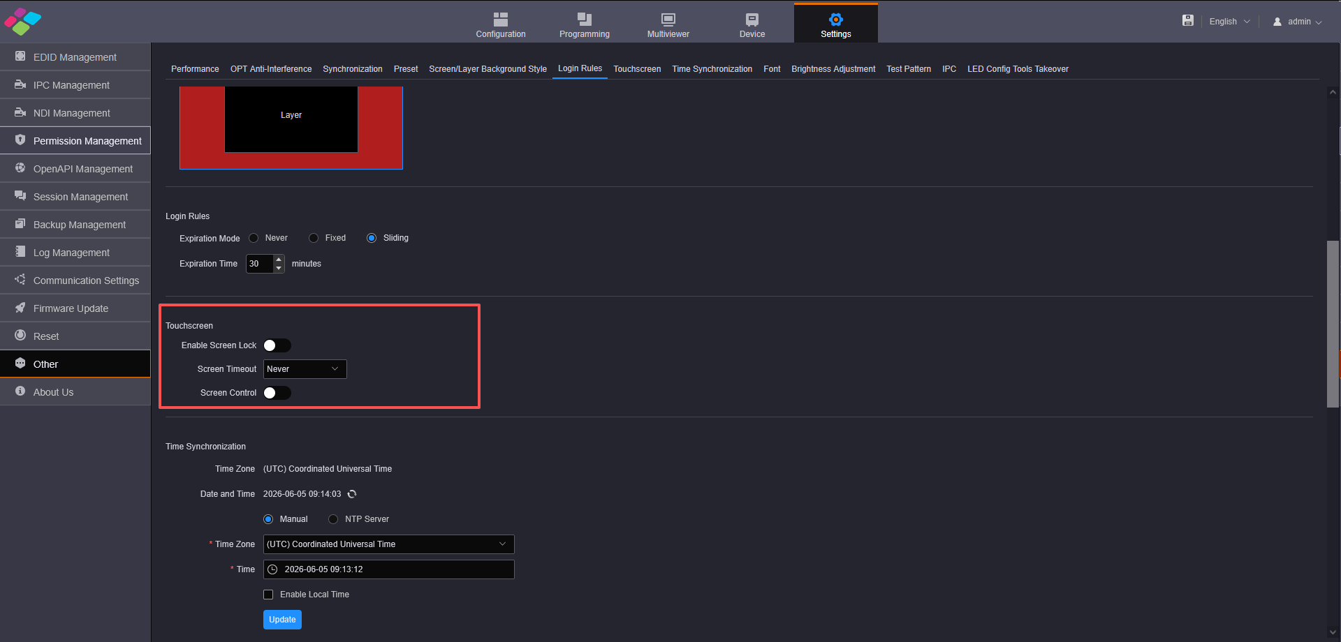
Touchscreen
Time Synchronization
- Step 1: Go to Settings > Other to enter the other settings page.
- Step 2: Click Time Synchronization at the top to enter the time synchronization page.
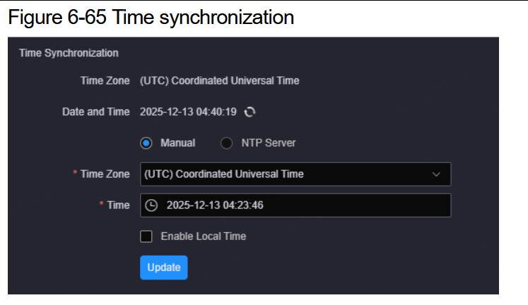
Time synchronization
You can view the time zone of the system server and current time.
- Step 3: Select the time synchronization method. The supported options include Manual and NTP Server.
Manual Time Synchronization
Manually select the time zone and time.
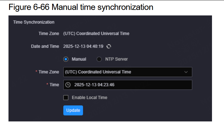
Manual time sync
- Time Zone: Select the server time zone from the drop-down list.
- Time: Set the current time.
- After you check the box next to Enable Local Time, the system will automatically update the time zone and time. Manual configuration is not allowed.
Click Update and the system will automatically update the time zone and time.
Time Synchronization via NTP Server
Obtain the time information via NTP server.
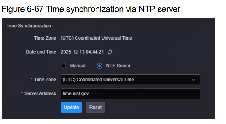
NTP server
- Time Zone: Select the server time zone from the drop-down list.
- Server Address: Enter the IP address or domain name of the time server.
Click Update and the system will automatically update the time zone and time based on the set server.
Text Font
The H series supports uploading local text fonts to the system, and the uploaded fonts can be used for OSD font settings.
- Add: Click + to select the font files to be added in the popup dialog. Click Open to upload the selected fonts to the system.
- Delete: In the font list, check the box in front of the font name, and then click trash can logo to delete the selected font, but the built-in font cannot be deleted.
⚠️ Note: Please pay attention to copyright issues when adding non-free fonts.
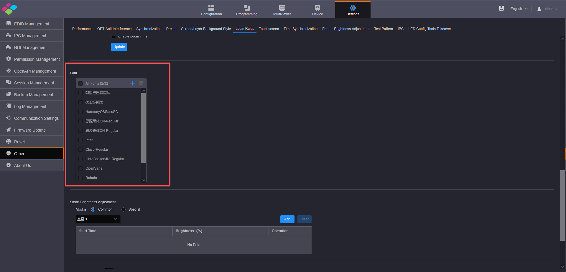
Text font
Brightness Adjustment
When the device is used to load an LED screen, the system will automatically adjust the screen brightness according to the set time and brightness value.
You need to select the adjustment mode according to the used module chip.
-
Common: Except for the 2153 module chip, other chips not used for special adjustment.
-
Special: Only for the 2153 module chip.
-
Step 1: Go to Settings > Other to enter the other settings page.
-
Step 2: In the Smart Brightness Adjustment area, select the adjustment mode according to the used module chip.
-
Step 3: Select the desired screen from the drop-down list.
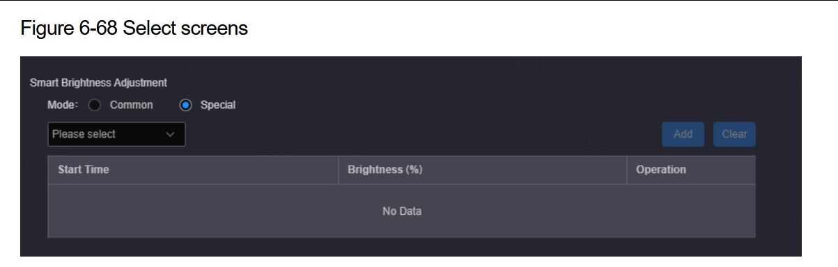
Brightness adjustment screen
- Step 4: Click Add to open the brightness adjustment settings window.
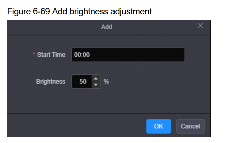
Brightness adjustment window
- Step 5: Set the adjustment start time.
- Step 6: Set the target brightness value. The value ranges from 0 to 100.
- Step 7: Click OK to complete the adding.
- Step 8: Repeat Step 4 to Step 7 to add new adjustment.
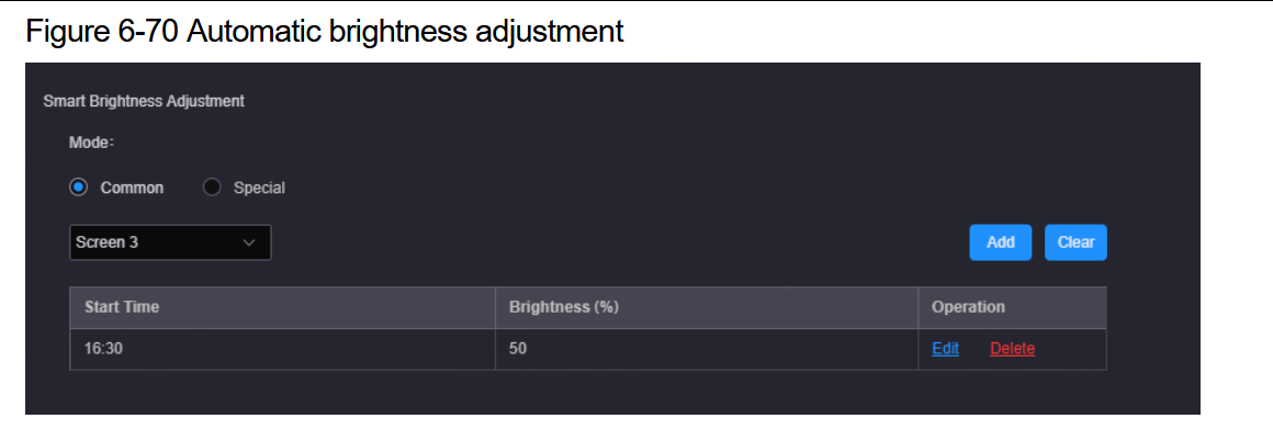
Brightness schedule list
Test Pattern Border
Display or hide the test pattern border.
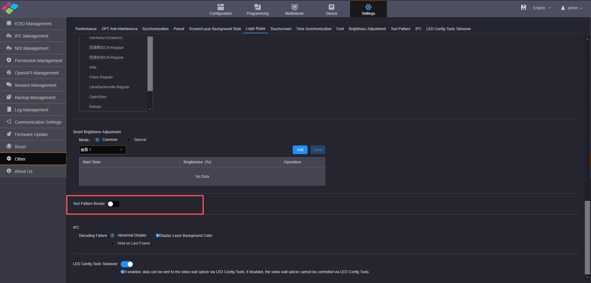
Test pattern border
IPC
Set the image display mode when IPC decoding fails.
- Abnormal Display: "No signal" will be displayed in the layer editing area and the layer background color will be enabled.
- Stay on Last Frame: Display the normal last frame image before decoding failure.
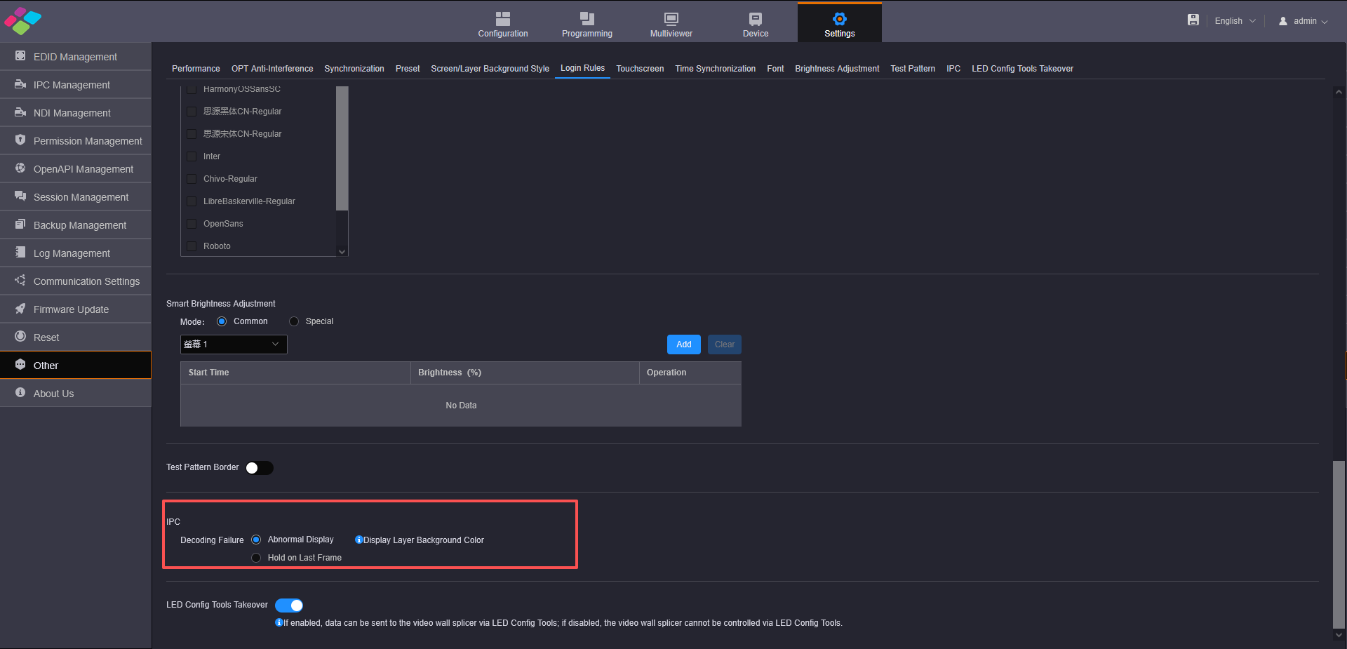
IPC settings
LED Config Tools Takeover
Enable or disable LED Config Tools Takeover.
- Enable: Send the screen configuration data to the H series via LED Config Tools.
- Disable: Disable the control of the H series via LED Config Tools.
About Us
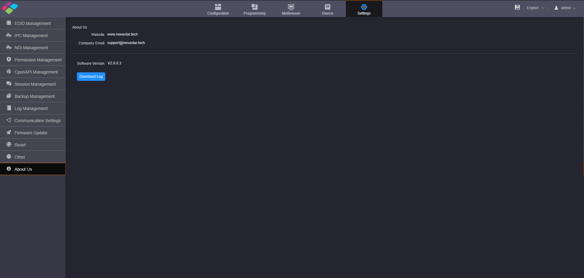
On this page, you can view the information such as the official website, email address and device version. Click Download Log to download the device operation log. When the device fails, you can download the log and send it to your device manufacturer for analyzing problems and offering suggestions to fix the problems.
About Us
3.9. H API
The H series provides the open API connector. The third-party developers can control video wall splicers through this connector. For more specific instructions and commands, please refer to the following link: Instructions - H Series OpenAPI Instructions.
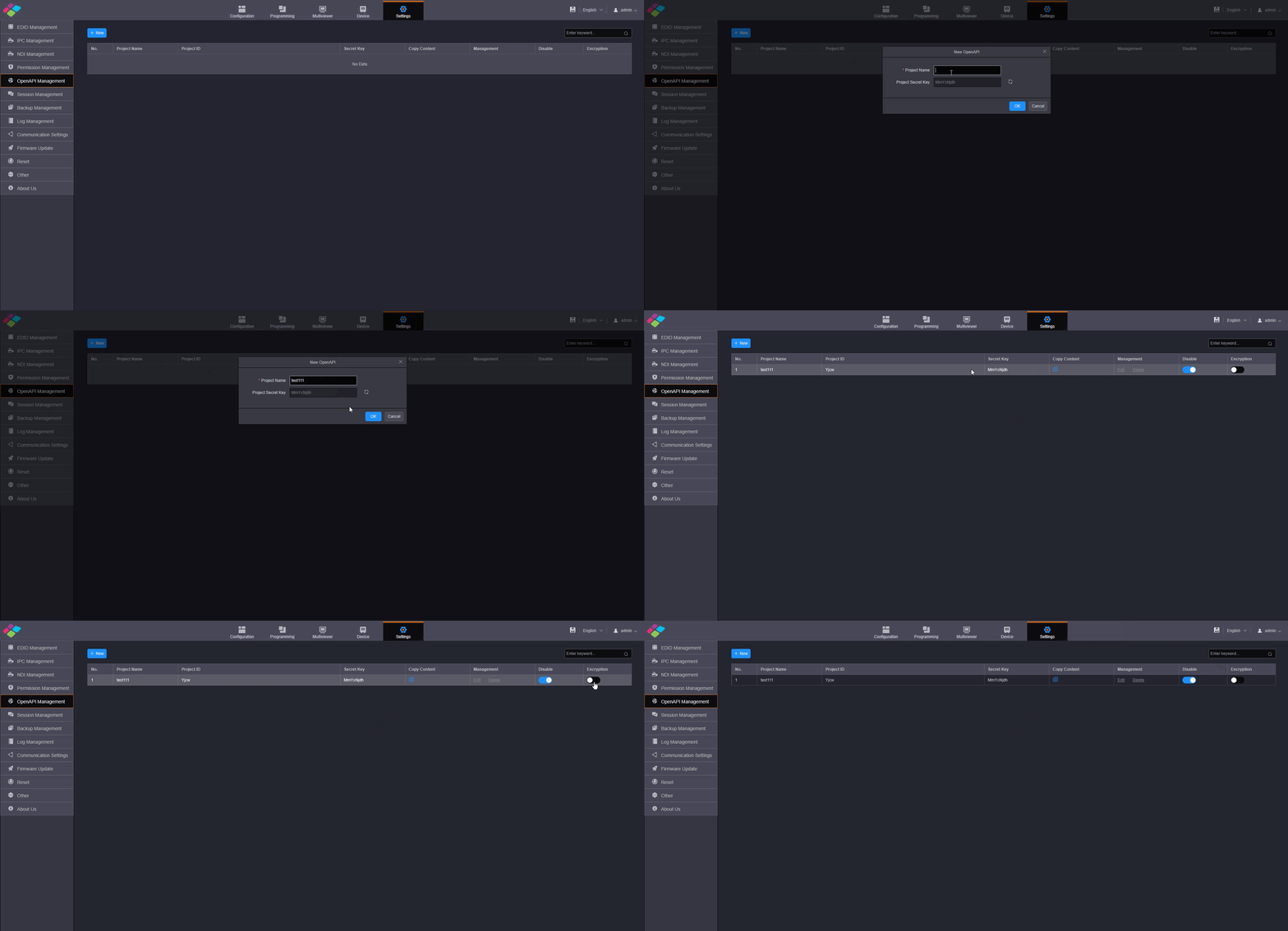
- Step 1: Click Open API Management on the left to enter the open API management page.

Open API management
- Step 2: Click Add to add a new open API project.
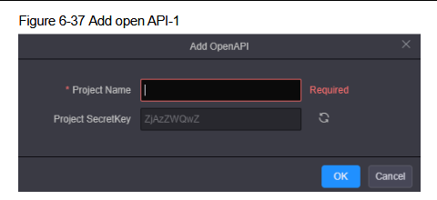
Add project
- Step 3: Enter the name of the third-party control in the Project Name text box. The system automatically generates a secret key and display it in the Project Secret Key text box. Click to generate a new key.
- Step 4: Click OK to complete the adding.
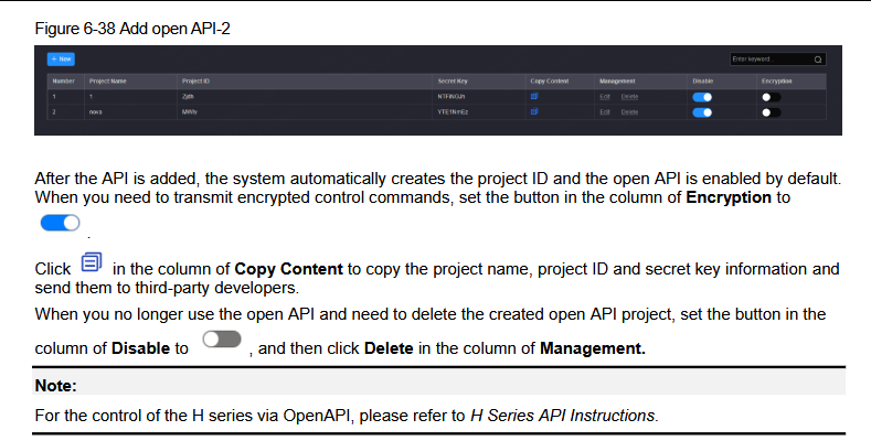
Project added
Open API overview